
User Manual
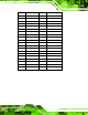
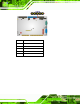
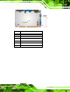

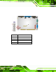
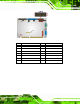
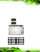
Table Of Contents
- 1 Introduction
- 2 Unpacking
- 3 Connectors
- 3.1 Peripheral Interface Connectors
- 3.2 Internal Peripheral Connectors
- 3.2.1 ATX Power Enable Connector
- 3.2.2 Audio Connector (10-pin)
- 3.2.3 Backlight Inverter Connector
- 3.2.4 Battery Connector
- 3.2.5 CompactFlash® Socket
- 3.2.6 Digital Input/Output (DIO) Connector
- 3.2.7 Fan Connector (+5V)
- 3.2.8 Floppy Disk Connector
- 3.2.9 Front Panel Connector (8-pin)
- 3.2.10 IDE Connector (40-pin)
- 3.2.11 Infrared Interface Connector (5-pin)
- 3.2.12 Keyboard/Mouse Connector
- 3.2.13 Parallel Port Connector
- 3.2.14 Power Connector
- 3.2.15 SATA Drive Connectors (Optional)
- 3.2.16 Serial Port Connector (RS-232/422/485)
- 3.2.17 TTL Connector
- 3.2.18 Internal USB Connectors
- 3.2.19 -VCC Power Connector
- 3.3 External Peripheral Interface Connectors
- 4 Installation
- 5 BIOS Screens
- A BIOS Menu Options
- B One Key Recovery
- C Terminology
- D Watchdog Timer
- E Hazardous Materials Disclosure
IOWA-LX-600 Half-size CPU Card
Page 36
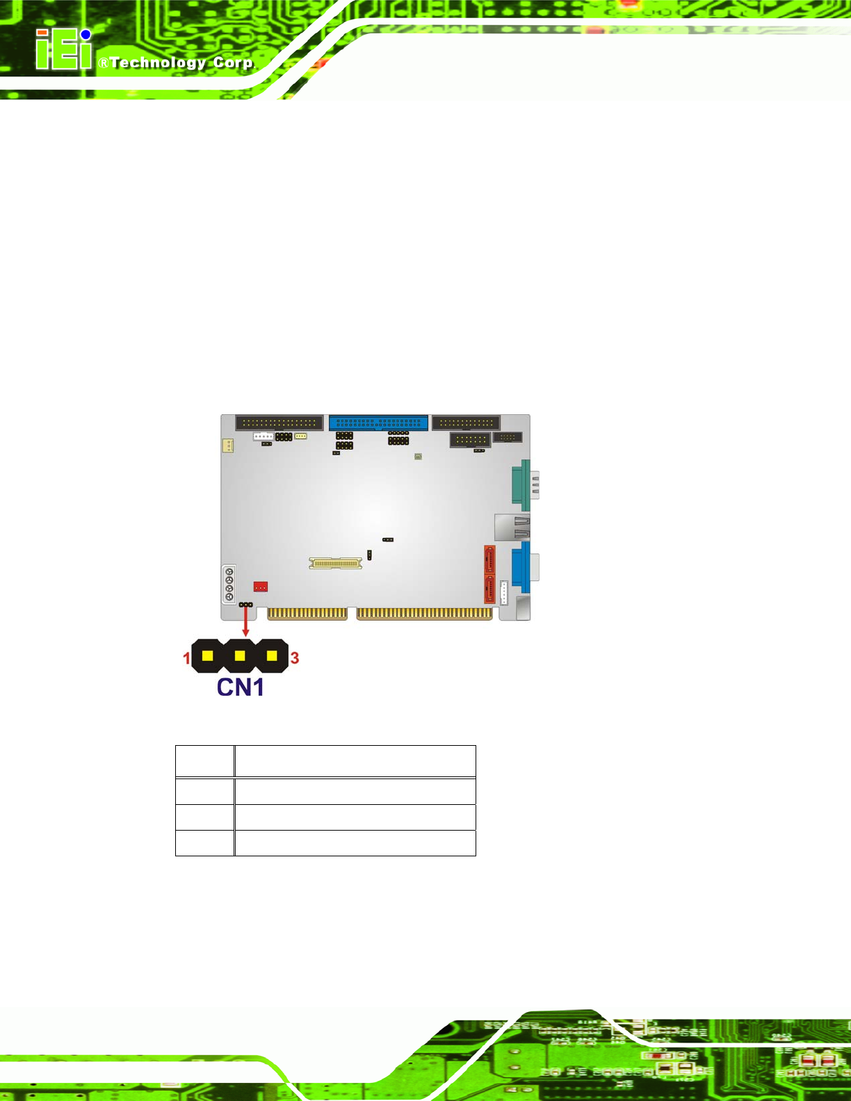
3.2.19 -VCC Power Connector
CN Label:
CN1
CN Type:
3-pin header (1x3)
CN Location:
See
6Figure 3-19
CN Pinouts:
See
6Table 3-20
The –VCC power connector provides –5V and –12V power to legacy expansion ISA
devices installed on the backplane. The power supply is connected to the –VCC power
connecter and transmitted to the ISA devices through the backplane.
Figure 3-20: -VCC Power Connector Pinout Locations
PIN DESCRIPTION
1 -5V
2 GROUND
3 -12V
Table 3-21: -VCC Power Connector Pinouts