
User Manual
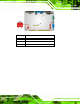
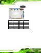
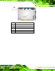
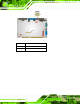
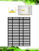
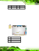
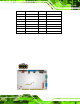
Table Of Contents
- 1 Introduction
- 2 Unpacking
- 3 Connectors
- 3.1 Peripheral Interface Connectors
- 3.2 Internal Peripheral Connectors
- 3.2.1 ATX Power Enable Connector
- 3.2.2 Audio Connector (10-pin)
- 3.2.3 Backlight Inverter Connector
- 3.2.4 Battery Connector
- 3.2.5 CompactFlash® Socket
- 3.2.6 Digital Input/Output (DIO) Connector
- 3.2.7 Fan Connector (+5V)
- 3.2.8 Floppy Disk Connector
- 3.2.9 Front Panel Connector (8-pin)
- 3.2.10 IDE Connector (40-pin)
- 3.2.11 Infrared Interface Connector (5-pin)
- 3.2.12 Keyboard/Mouse Connector
- 3.2.13 Parallel Port Connector
- 3.2.14 Power Connector
- 3.2.15 SATA Drive Connectors (Optional)
- 3.2.16 Serial Port Connector (RS-232/422/485)
- 3.2.17 TTL Connector
- 3.2.18 Internal USB Connectors
- 3.2.19 -VCC Power Connector
- 3.3 External Peripheral Interface Connectors
- 4 Installation
- 5 BIOS Screens
- A BIOS Menu Options
- B One Key Recovery
- C Terminology
- D Watchdog Timer
- E Hazardous Materials Disclosure
IOWA-LX-600 Half-size CPU Card
Page 25
PIN DESCRIPTION PIN DESCRIPTION
19 GROUND 20 STEP#
21 GROUND 22 WDATA#
23 GROUND 24 WGATE#
25 GROUND 26 TRK0#
27 GROUND 28 WP#
29 N/C 30 RDATA#
31 GROUND 32 HDSEL#
33 N/C 34 DSKCHG#
Table 3-10: FDD Connector Pinouts
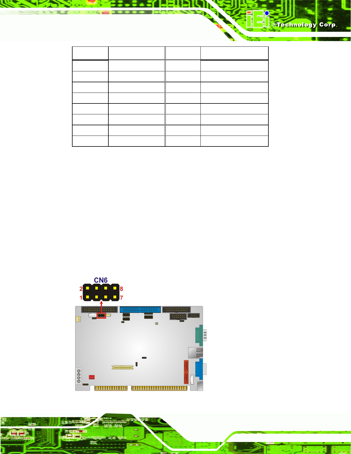
3.2.9 Front Panel Connector (8-pin)
CN Label:
CN6
CN Type:
8-pin header (2x4)
CN Location:
See
5Figure 3-10
CN Pinouts:
See
5Table 3-11
The front panel conne cto r con ne cts to the po we r b utton, reset b utton an d hard drive LE Ds
located on the front panel of the chassis.
Figure 3-10: Front Panel Connector Pinout Locations