
User Manual
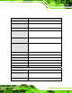
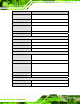

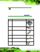
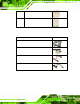

Table Of Contents
- 1 Introduction
- 2 Unpacking
- 3 Connectors
- 3.1 Peripheral Interface Connectors
- 3.2 Internal Peripheral Connectors
- 3.2.1 ATX Power Enable Connector
- 3.2.2 Audio Connector (10-pin)
- 3.2.3 Backlight Inverter Connector
- 3.2.4 Battery Connector
- 3.2.5 CompactFlash® Socket
- 3.2.6 Digital Input/Output (DIO) Connector
- 3.2.7 Fan Connector (+5V)
- 3.2.8 Floppy Disk Connector
- 3.2.9 Front Panel Connector (8-pin)
- 3.2.10 IDE Connector (40-pin)
- 3.2.11 Infrared Interface Connector (5-pin)
- 3.2.12 Keyboard/Mouse Connector
- 3.2.13 Parallel Port Connector
- 3.2.14 Power Connector
- 3.2.15 SATA Drive Connectors (Optional)
- 3.2.16 Serial Port Connector (RS-232/422/485)
- 3.2.17 TTL Connector
- 3.2.18 Internal USB Connectors
- 3.2.19 -VCC Power Connector
- 3.3 External Peripheral Interface Connectors
- 4 Installation
- 5 BIOS Screens
- A BIOS Menu Options
- B One Key Recovery
- C Terminology
- D Watchdog Timer
- E Hazardous Materials Disclosure
IOWA-LX-600 Half-size CPU Card
Page 12
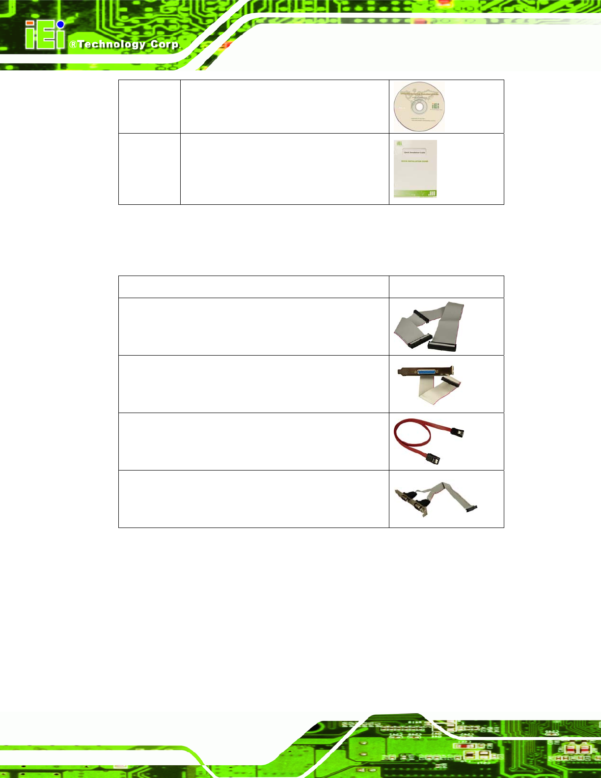
1 Utility CD
1 Quick Installa tion Guide
2.3.1 Optional Items
The following are optional comp onents which may be separately p urchased:
Item and Part Number Image
FDD cable
(P/N: 32200-000017-RS)
Parallel port cable
(P/N:19800-000400-100-RS)
SATA cable
(P/N: 32000-062800-RS)
Dual RS-232/422/485 cabl e
(P/N: 19800-000058-RS)