
User Manual
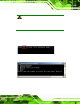
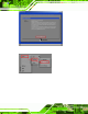
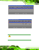
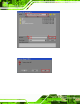
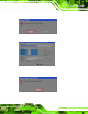
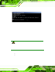
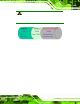
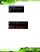
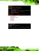
Table Of Contents
- 1 Introduction
- 2 Unpacking
- 3 Connectors
- 3.1 Peripheral Interface Connectors
- 3.2 Internal Peripheral Connectors
- 3.2.1 ATX Power Enable Connector
- 3.2.2 Audio Connector (10-pin)
- 3.2.3 Backlight Inverter Connector
- 3.2.4 Battery Connector
- 3.2.5 CompactFlash® Socket
- 3.2.6 Digital Input/Output (DIO) Connector
- 3.2.7 Fan Connector (+5V)
- 3.2.8 Floppy Disk Connector
- 3.2.9 Front Panel Connector (8-pin)
- 3.2.10 IDE Connector (40-pin)
- 3.2.11 Infrared Interface Connector (5-pin)
- 3.2.12 Keyboard/Mouse Connector
- 3.2.13 Parallel Port Connector
- 3.2.14 Power Connector
- 3.2.15 SATA Drive Connectors (Optional)
- 3.2.16 Serial Port Connector (RS-232/422/485)
- 3.2.17 TTL Connector
- 3.2.18 Internal USB Connectors
- 3.2.19 -VCC Power Connector
- 3.3 External Peripheral Interface Connectors
- 4 Installation
- 5 BIOS Screens
- A BIOS Menu Options
- B One Key Recovery
- C Terminology
- D Watchdog Timer
- E Hazardous Materials Disclosure
IOWA-LX-600 Half-size CPU Card
Page 123
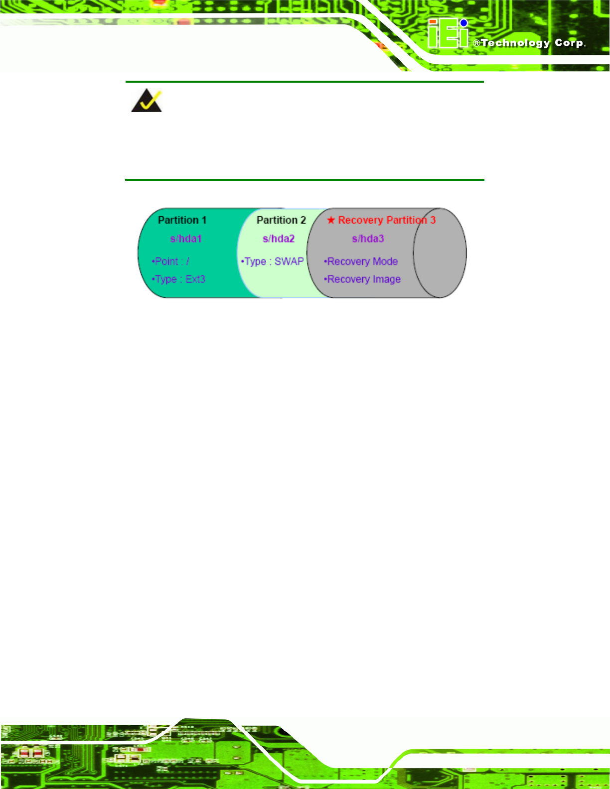
NOTE:
Please reserve enough space for partition 3 for saving recovery
images.
Figure B-22: Partitions for Linux
Step 3: Create a recovery partition. Insert the recovery CD into the optical disk drive.
Follow Step 1 ~ Step 3 described in Section
777B.2.2. Then type the following
commands (marked in red) to create a partition for recovery images.
system32>diskpart
DISKPART>list vol
DISKPART>sel disk 0
DISKPART>crea te part pri size= ___
DISKPART>assign letter =N
DISKPART>exit
system32>format N: /fs:ntfs /q /v:Recovery /y
system32>exit
Step 4: Build-up recovery p artition. Press an y key to boot from the reco very CD. It will
take a while t o launch the recovery tool. Please be pat ient. When the recovery
tool setup menu appears, type <3> and press <Enter> (
787Figure B-23). The
Symantec Ghost window appears and st art s configuring the system to build-u p a
recovery partit ion. Af ter completing the system configuration, pre ss any key to
reboot the system. Eject the recovery CD.