
User Manual
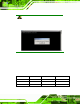

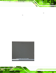
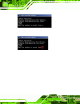
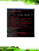
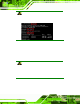
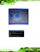
Table Of Contents
- 1 Introduction
- 2 Unpacking
- 3 Connectors
- 3.1 Peripheral Interface Connectors
- 3.2 Internal Peripheral Connectors
- 3.2.1 ATX Power Enable Connector
- 3.2.2 Audio Connector (10-pin)
- 3.2.3 Backlight Inverter Connector
- 3.2.4 Battery Connector
- 3.2.5 CompactFlash® Socket
- 3.2.6 Digital Input/Output (DIO) Connector
- 3.2.7 Fan Connector (+5V)
- 3.2.8 Floppy Disk Connector
- 3.2.9 Front Panel Connector (8-pin)
- 3.2.10 IDE Connector (40-pin)
- 3.2.11 Infrared Interface Connector (5-pin)
- 3.2.12 Keyboard/Mouse Connector
- 3.2.13 Parallel Port Connector
- 3.2.14 Power Connector
- 3.2.15 SATA Drive Connectors (Optional)
- 3.2.16 Serial Port Connector (RS-232/422/485)
- 3.2.17 TTL Connector
- 3.2.18 Internal USB Connectors
- 3.2.19 -VCC Power Connector
- 3.3 External Peripheral Interface Connectors
- 4 Installation
- 5 BIOS Screens
- A BIOS Menu Options
- B One Key Recovery
- C Terminology
- D Watchdog Timer
- E Hazardous Materials Disclosure

IOWA-LX-600 Half-size CPU Card
Page 112
Step 3: The recovery tool setup menu is shown as below.
Figure B-3: Recovery Tool Setup Me nu
Step 4: Press <5> then <Enter>.
Figure B-4: Command Mode
Step 5: The command prompt window appears. Type the following commands (marked
in red) to create two partitions. One is for the OS installation; the other is for
saving recovery files and images which will be an invisible partition.
(Press <Enter> after entering each line below)
system32>diskpart
DISKPART>list vol
DISKPART>sel disk 0
DISKPART>crea te part pri size= ___
DISKPART>assign letter =N
DISKPART>crea te part pri size= ___
DISKPART>assign letter =F
DISKPART>exit
system32>format N: /fs:ntfs /q /y