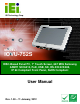
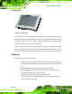
IOVU-752S Panel PC IEI Technology Corp. MODEL: IOVU-752S RISC-Based Panel PC, 7" Touch Screen, 667 MHz Samsung ARM11 S3C6410, PoE, USB, SD, RS-232/422/485, IP 64 Compliant Front Panel, RoHS Compliant User Manual Page i Rev. 1.
IOVU-752S Panel PC Revision Date Version Changes 11 January, 2012 1.
IOVU-752S Panel PC Copyright COPYRIGHT NOTICE The information in this document is subject to change without prior notice in order to improve reliability, design and function and does not represent a commitment on the part of the manufacturer. In no event will the manufacturer be liable for direct, indirect, special, incidental, or consequential damages arising out of the use or inability to use the product or documentation, even if advised of the possibility of such damages.
IOVU-752S Panel PC Table of Contents 1 INTRODUCTION.......................................................................................................... 1 1.1 OVERVIEW.................................................................................................................. 2 1.2 BENEFITS ................................................................................................................... 2 1.3 FEATURES ..............................................................................
IOVU-752S Panel PC 3.4.1 Wall Mounting.................................................................................................. 22 3.4.2 Panel Mounting................................................................................................ 25 3.4.3 Arm Mounting .................................................................................................. 27 3.4.4 Stand Mounting ................................................................................................ 28 3.
IOVU-752S Panel PC List of Figures Figure 1-1: IOVU-752S....................................................................................................................2 Figure 1-2: IOVU-752S Front Panel ...............................................................................................3 Figure 1-3: IOVU-752S Peripheral Connectors ............................................................................4 Figure 1-4: IOVU-752S Physical Dimensions (millimeters) ............................
IOVU-752S Panel PC List of Tables Table 1-1: Technical Specifications..............................................................................................7 Table 2-1: Package List Contents ...............................................................................................10 Table 2-2: Optional Items.............................................................................................................11 Table 3-1: External Interface Connectors......................................
IOVU-752S Panel PC Chapter 1 1 Introduction Page 1
IOVU-752S Panel PC 1.1 Overview Figure 1-1: IOVU-752S The IOVU-752S is an RISC-based panel PC that features a 667 MHz Samsung ARM11 S3C6410 processor and has 256 MB DDR2 memory. The IOVU-752S provides rich input capabilities utilizing the touch screen. Output capabilities are provided through RS-232/422/485 ports, network port and USB ports. The IOVU-752S is an extremely low power Panel PC. The system is fanless, which allows quiet and reliable operation. The IOVU-752S is preinstalled with Windows® CE 6.
IOVU-752S Panel PC 1.3 Features The IOVU-752S features are listed below: Embedded 667 MHz Samsung ARM11 S3C6410 processor 128 MB Nand Flash On-board 256 MB DDR2 memory Supports MPEG 1, MPEG 2, MPEG 4 and WMV 9 video file formats 7" color active matrix TFT display 4-wire resistive touch panel One high performance 10/100 Mb/s Ethernet connector with PoE (Power over Ethernet) capability Preinstalled with Windows® CE 6.0 OS Two USB 2.
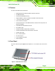
IOVU-752S Panel PC 1.5 Connector Panel The external peripheral interface connectors are located on the bottom panel of the IOVU-752S . The peripheral interface connectors are shown in Figure 1-3.
IOVU-752S Panel PC 1.
IOVU-752S Panel PC 1.8 Technical Specifications The IOVU-752S technical specifications are listed in Table 1-1. Specifications System CPU 667 MHz Samsung ARM11 S3C6410 processor 128 MB Nand Flash Memory 256 MB DDR2 Operating System Windows® CE 6.0 preinstalled Real-time Clock Battery backup RTC Watchdog Timer Software programmable supports 1~255 sec.
IOVU-752S Panel PC Specifications Power Power Supply 9 V~30 V DC input by power jack and terminal block Power Consumption 14 W Environmental and Mechanical Operating Temperature 0ºC~ 50°C Humidity 5%RH to 90%RH (non-condensing) Operating Random Vibration Mode (MIL-STD-810F 514.5C-3) 1.Axes: 3 axes (Vertical / Transverse / Longitudinal). Vibration 2.10-500 Hz, 60min/axis. 3.Equivalent to Z:2.18 Grms X:1.6 Grms Y:1.
IOVU-752S Panel PC Chapter 2 2 Unpacking Page 8
IOVU-752S Panel PC 2.1 Anti-static Precautions WARNING: Failure to take ESD precautions during installation may result in permanent damage to the IOVU-752S and severe injury to the user. Electrostatic discharge (ESD) can cause serious damage to electronic components, including the IOVU-752S. Dry climates are especially susceptible to ESD. It is therefore critical that whenever the IOVU-752S or any other electrical component is handled, the following anti-static precautions are strictly adhered to.
IOVU-752S Panel PC 2.3 Unpacking Checklist NOTE: If some of the components listed in the checklist below are missing, please do not proceed with the installation. Contact the IEI reseller or vendor you purchased the IOVU-752S from or contact an IEI sales representative directly. To contact an IEI sales representative, please send an email to sales@iei.com.tw.
IOVU-752S Panel PC 2.4 Optional Items Item and Part Number Image Panel mount kit (P/N: ALFPK-08) VESA 75 wall mount kit (P/N: AFLWK-07) LCD monitor/PPC arm kit, load capacity of 3kg~7kg (P/N: ARM-11-RS) LCD monitor/PPC stand kit for VESA 75, up to 5kg (P/N: STAND-A08-RS) LCD monitor/PPC stand V type for VESA 75, 0~90 degree adjustable hinge and up to 2.
IOVU-752S Panel PC Chapter 3 3 Installation Page 12
IOVU-752S Panel PC 3.1 Installation Precautions During installation, be aware of the precautions below: Read the user manual: The user manual provides a complete description of the IOVU-752S, installation instructions and configuration options. DANGER! Disconnect Power: Power to the IOVU-752S must be disconnected during the installation process, or before any attempt is made to access the rear panel.
IOVU-752S Panel PC 3.2 SD Card Installation The IOVU-752S supports an SD card. Follow the steps below to install an SD card. Step 1: Remove the rear panel by removing the 10 retention screws from the rear panel (Figure 3-1). Figure 3-1: Rear Panel Retention Screws Step 2: Locate the SD card slot on the motherboard (Figure 3-2). Step 3: Slide the SD card into the slot (Figure 3-2). Figure 3-2: SD Card Installation Step 4: Reinstall the rear panel.
IOVU-752S Panel PC 3.3 External Peripheral Interface Connectors Table 3-1 lists the external interface connectors on the IOVU-752S. Detailed descriptions of the connectors can be found following the table.
IOVU-752S Panel PC 3.3.1.2 9 V~30 V DC Terminal Block The power terminal block connects to a 9 V~30 V DC power source. CN Label: 9-30V DC CN Type: Terminal block CN Location: See Figure 3-3 CN Pinouts: See Table 3-2 and Figure 3-4 Pin Description 1 9 V~30 V DC Power in 2 GND Table 3-2: 9 V~30 V Power Connector Pinouts Figure 3-4: Power Terminal Block 3.3.2 Ethernet Connector There is one external RJ-45 LAN connector. The RJ-45 connectors enable connection to an external network.
IOVU-752S Panel PC Figure 3-5: LAN Connection Step 2: Insert the LAN cable RJ-45 connector. Once aligned, gently insert the LAN cable RJ-45 connector into the on-board RJ-45 connector. Step 0: The Ethernet connector pinouts are shown below.
IOVU-752S Panel PC The RJ-45 Ethernet connector has two status LEDs, one green and one yellow. The green LED indicates activity on the port and the yellow LED indicates the port is linked (Table 3-4). SPEED LED LINK LED Status Description Status Description GREEN ON: 100 MB YELLOW ON: Linked OFF: 10 MB Flashing: Activity Table 3-4: Ethernet Connector LEDs 3.3.3 Serial Interfaces The system has both a RS-232 and a RS-232/422/485 serial port connector. 3.3.3.
IOVU-752S Panel PC 3.3.3.2 RS-232/422/485 Serial Interface Pinouts Pinouts for the RS-232/422/485 serial port are shown below. Pin RS-232 1 RS-422 RS-485 RX- DATADATA+ 2 RX RX+ 3 TX TX- GND GND 4 5 GND 6 7 TX+ 8 9 Table 3-6: Serial Port Pinouts Figure 3–7: Serial Port Pinouts To select RS-232, RS-422, or RS-485 mode, please follow the directions below. Step 1: Select "Start > Programs > IEI > IEI CEUTILITY.exe" to run IEI_CEUTILITY.exe.
IOVU-752S Panel PC Figure 3-8: Serial Port Mode Setting Step 2: Change serial port mode setting. Change the value in Figure 3-8 to the desired mode setting. Step 3: Click "Save Registry" to save the changes. Step 0: 3.3.3.3 Connecting the Serial Port Follow the steps below to connect a serial device to the IOVU-752S. Step 1: Insert the serial connector. Insert the DB-9 connector of a serial device into the DB-9 connector on the external peripheral interface. See Figure 3-9.
IOVU-752S Panel PC Figure 3-9: Serial Device Connector Step 2: Secure the connector. Secure the serial device connector to the external interface by tightening the two retention screws on either side of the connector. Step 0: 3.3.4 USB Connectors The external USB Series "A" receptacle connector provides easier and quicker access to external USB devices. Follow the steps below to connect USB devices to the IOVU-752S. Step 1: Insert a USB Series "A" plug.
IOVU-752S Panel PC USB devices connect directly to the USB connector on the external peripheral connector panel. Pin Description Pin Description 1 VCC 5 VCC 2 D1- 6 D2- 3 D1+ 7 D2+ 4 GND 8 GND Table 3-7: USB Connector Pinouts 3.4 Mounting the System WARNING! When mounting the panel PC, it is better to have more than one person to help with the installation to make sure the panel PC does not fall down and get damaged. Four methods of mounting the IOVU-752S are listed below.
IOVU-752S Panel PC Step 4: Align the wall-mounting bracket screw holes with the pilot holes. Step 5: Secure the mounting-bracket to the wall by inserting the retention screws into the four pilot holes and tightening them (Figure 3-11). Figure 3-11: Wall-mounting Bracket Step 6: Insert the four monitor mounting screws provided in the wall mounting kit into the four screw holes on the real panel of the IOVU-752S and tighten until the screw shank is secured against the rear panel (Figure 3-12).
IOVU-752S Panel PC Figure 3-12: Chassis Support Screws Step 9: Secure the panel PC by fastening the retention screw of the wall-mounting bracket (Figure 3-13).
IOVU-752S Panel PC 3.4.2 Panel Mounting The IOVU-752S can be mounted in a panel. CAUTION: When mounting the IOVU-752S, take care to tighten the retention screws or bolts until fully secure, but do not over tighten. Over tightening the retention screws or bolts may cause them to become stripped, rendering them useless. To mount the IOVU-752S into a panel, please follow the steps below. Step 1: Select the position on the panel to mount the IOVU-752S.
IOVU-752S Panel PC Step 4: Insert the panel mounting clamps into the pre-formed holes along the edges of the chassis, behind the frame. Figure 3-15: Panel Mounting Clamps Step 5: Tighten the screws that pass through the panel mounting clamps until the plastic caps at the front of all the screws are firmly secured to the panel (Figure 3-16).
IOVU-752S Panel PC 3.4.3 Arm Mounting The IOVU-752S is VESA (Video Electronics Standards Association) compliant and can be mounted on an arm with a 75 mm interface pad. To mount the IOVU-752S on an arm, please follow the steps below. Step 1: The arm is a separately purchased item. Please correctly mount the arm onto the surface it uses as a base. To do this, refer to the installation documentation that came with the mounting arm.
IOVU-752S Panel PC Step 4: Secure the IOVU-752S to the interface pad by inserting four retention screws through the bottom of the mounting arm interface pad and into the IOVU-752S. Figure 3-18: Arm Mounting Retention Screw Holes 3.4.4 Stand Mounting The IOVU-752S has Video Electronics Standards Association (VESA) standard mounting holes tapped into the rear panel. The monitor stand mounting plate has a matching VESA hole pattern. To mount the IOVU-752S onto a stand, please follow the steps below.
IOVU-752S Panel PC Figure 3-19: Stand Mounting 3.5 Software The IOVU-752S comes with a pre-installed Windows® CE 6.0 operating system and a rich software application development kit. For information about configuring the operating system, adding remote management tools or additional software and drivers, refer to the user manuals on IEI IOVU Utility CD that came with the IOVU-752S. The IOVU includes the following software: Standard Windows® CE 6.0 professional version license.
IOVU-752S Panel PC Appendix A A Certifications Page 30
IOVU-752S Panel PC A.1 RoHS Compliant All models in the IOVU series comply with the Restriction of Hazardous Materials (RoHS) Directive. This means that all components used to build the industrial workstations and the workstation itself are RoHS compliant.
IOVU-752S Panel PC Appendix B B Safety Precautions Page 32
IOVU-752S Panel PC B.1 Safety Precautions WARNING: The precautions outlined in this appendix should be strictly followed. Failure to follow these precautions may result in permanent damage to the IOVU-752S. Please follow the safety precautions outlined in the sections that follow: B.1.1 General Safety Precautions Please ensure the following safety precautions are adhered to at all times.
IOVU-752S Panel PC B.1.2 Anti-static Precautions WARNING: Failure to take ESD precautions during the installation of the IOVU-752S may result in permanent damage to the IOVU-752S and severe injury to the user. Electrostatic discharge (ESD) can cause serious damage to electronic components, including the IOVU-752S. Dry climates are especially susceptible to ESD.
IOVU-752S Panel PC B.1.3 Product Disposal CAUTION: Risk of explosion if battery is replaced by and incorrect type. Only certified engineers should replace the on-board battery. Dispose of used batteries according to instructions and local regulations. Outside the European Union - If you wish to dispose of used electrical and electronic products outside the European Union, please contact your local authority so as to comply with the correct disposal method.
IOVU-752S Panel PC Except for the LCD panel, never spray or squirt liquids directly onto any other components. To clean the LCD panel, gently wipe it with a piece of soft dry cloth or a slightly moistened cloth. The interior of the IOVU-752S does not require cleaning. Keep fluids away from the IOVU-752S interior. Be cautious of all small removable components when vacuuming the IOVU-752S. Turn the IOVU-752S off before cleaning the IOVU-752S.
IOVU-752S Panel PC B.3 FCC Precautions WARNING: This device complies with Part 15 of the FCC Rules. Operation is subject to the following two conditions: (1) this device may not cause harmful interference, and(2) this device must accept any interference received, including interference that may cause undesired operation. NOTE: This equipment has been tested and found to comply with the limits for a Class B digital device, pursuant to part 15 of the FCC Rules.
IOVU-752S Panel PC Appendix C C Hazardous Materials Disclosure Page 38
IOVU-752S Panel PC C.1 Hazardous Materials Disclosure Table for IPB Products Certified as RoHS Compliant Under 2002/95/EC Without Mercury The details provided in this appendix are to ensure that the product is compliant with the Peoples Republic of China (China) RoHS standards. The table below acknowledges the presences of small quantities of certain materials in the product, and is applicable to China RoHS only.
IOVU-752S Panel PC Part Name Toxic or Hazardous Substances and Elements Lead Mercury Cadmium Hexavalent Polybrominated Polybrominated (Pb) (Hg) (Cd) Chromium Biphenyls Diphenyl (CR(VI)) (PBB) Ethers (PBDE) Housing X O O O O X Display X O O O O X Printed Circuit X O O O O X X O O O O O X O O O O X Fan Assembly X O O O O X Power Supply X O O O O X O O O O O O Board Metal Fasteners Cable Assembly Assemblies Battery O: This toxic or hazardou
IOVU-752S Panel PC 此附件旨在确保本产品符合中国 RoHS 标准。以下表格标示此产品中某有毒物质的含量符 合中国 RoHS 标准规定的限量要求。 本产品上会附有”环境友好使用期限”的标签,此期限是估算这些物质”不会有泄漏或突变”的 年限。本产品可能包含有较短的环境友好使用期限的可替换元件,像是电池或灯管,这些元 件将会单独标示出来。 部件名称 有毒有害物质或元素 铅 汞 镉 六价铬 多溴联苯 多溴二苯 (Pb) (Hg) (Cd) (CR(VI)) (PBB) 醚 (PBDE) 壳体 X O O O O X 显示 X O O O O X 印刷电路板 X O O O O X 金属螺帽 X O O O O O 电缆组装 X O O O O X 风扇组装 X O O O O X 电力供应组装 X O O O O X 电池 O O O O O O O: 表示该有毒有害物质在该部件所有物质材料中的含量均在 SJ/T11363-2006 标准规定的限量要求以下。 X