
User guide

IOVU-572M Panel PC
Page 24
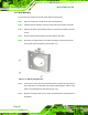
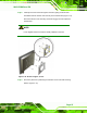
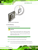
Figure 4-11: LAN Connection
Step 3: Insert the LAN cable RJ-45 connector. Once aligned, gently insert the LAN
cable RJ-45 connector into the on-board RJ-45 connector. Step 0:
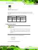
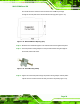
The Ethernet connector pinouts are shown below.
PIN DESCRIPTION
1 TPT+
2 TPT-
3 TPR+
4 LAN_GND
5 LAN_GND
6 TPR-
7 LAN_GND
8 LAN_GND
Table 4-5: Ethernet Connector Pinouts