
User guide

IOVU-572M Panel PC
Page 23
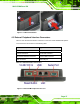
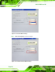
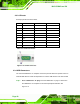
Figure 4-10: USB Connector
USB devices connect directly to the USB connectors on the external peripheral connector
panel.
Pin Description Pin
Description
1 VCC 5 VCC
2 D1- 6 D2-
3 D1+ 7 D2+
4 GND 8 GND
Table 4-4: USB Connector Pinouts
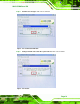
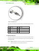
4.3.4 Ethernet Connector
There are two external RJ-45 LAN connectors. The RJ-45 connectors enable connection
to an external network. To connect a LAN cable with an RJ-45 connector, please follow
the instructions below.
Step 2: Align the connectors. Align the RJ-45 connector on the LAN cable with one of
the RJ-45 connectors on the IOVU-572M. See
Figure 4-11.