
User guide

IOVU-572M Panel PC
Page 22
Step 0:
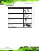
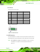
4.3.2.3 Pinouts
Serial port pinouts are shown below.
Pin RS-232 RS-422 RS-485
1 DCD RXD- DATA-
2 RX RXD+ DATA+
3 TX TXD-
4 DTR
5 GND GND GND
6 DSR
7 RTS TXD+
8 CTS
9 RI
Table 4-3: Serial Port Pinouts
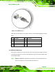
Figure 4–9: Serial Port Pinouts
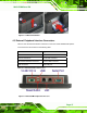
4.3.3 USB Connectors
The external USB Series "A" receptacle connectors provide easier and quicker access to
external USB devices. Follow the steps below to connect USB devices to the IOVU-572M.
Step 1: Insert a USB Series "A" plug. Insert the USB Series "A" plug of a device into
the USB Series "A" receptacle on the external peripheral interface. See
Figure 4-10. Step 1: