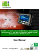
IOVU-572M Panel PC IEI Technology Corp. MODEL: IOVU-572M Panel PC, 5.7" Touch Screen, 624 MHz Marvell XScale PXA310, Fast Ethernet, 2 x USB, 802.11b/g Wireless, RS-232/422/485 RoHS Compliant, IP 64 Protection User Manual Page i Rev. 1.
IOVU-572M Panel PC Revision Date Version Changes 27 August, 2013 1.01 Added Section 4.5.1: Wireless AP 13 February, 2012 1.
IOVU-572M Panel PC Copyright COPYRIGHT NOTICE The information in this document is subject to change without prior notice in order to improve reliability, design and function and does not represent a commitment on the part of the manufacturer. In no event will the manufacturer be liable for direct, indirect, special, incidental, or consequential damages arising out of the use or inability to use the product or documentation, even if advised of the possibility of such damages.
IOVU-572M Panel PC Table of Contents 1 INTRODUCTION.......................................................................................................... 1 1.1 OVERVIEW.................................................................................................................. 2 1.2 BENEFITS ................................................................................................................... 2 1.3 FEATURES ..............................................................................
IOVU-572M Panel PC 4.4.1 Wall Mounting.................................................................................................. 26 4.4.2 Panel Mounting................................................................................................ 28 4.4.3 Arm Mounting .................................................................................................. 30 4.4.4 Stand Mounting ................................................................................................ 31 4.
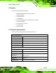
IOVU-572M Panel PC List of Figures Figure 1-1: IOVU-572M ...................................................................................................................2 Figure 2-1: Front Panel ..................................................................................................................7 Figure 2-2: IOVU-572M Peripheral Connectors ...........................................................................7 Figure 2-3: IOVU-572M Physical Dimensions (millimeters) ....................
IOVU-572M Panel PC List of Tables Table 1-1: Technical Specifications..............................................................................................4 Table 3-1: Package List Contents ...............................................................................................13 Table 3-2: Optional Items.............................................................................................................14 Table 4-1: External Interface Connectors......................................
IOVU-572M Panel PC Chapter 1 1 Introduction Page 1
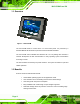
IOVU-572M Panel PC 1.1 Overview Figure 1-1: IOVU-572M The IOVU-572M Panel PC comes with a 5.7" touch screen panel. It is powered by a 624 MHz Marvell XScale PXA310 processor and has 256 MB of SDRAM. The IOVU-572M comes installed with Windows CE 6.0. The package also includes a software development kit and documentation for easy operating system customization according to needs. The IOVU-572M is an extremely low power Panel PC. The system is fanless for quiet and reliable operation 1.
IOVU-572M Panel PC 1.3 Features The IOVU-572M features are listed below: 624 MHz Marvell XScale PXA310 processor 256 MB of SDRAM Two Ethernet ports Two USB ports One RS-232/422/485 serial communication connection Two built-in speakers 4-wire resistive touch panel 12-36 VDC input RoHS compliant 1.4 Technical Specifications The IOVU-572M technical specifications are listed in Table 1-1.
IOVU-572M Panel PC I/O and Communications Ethernet 2 x 10/100 Mb/s Serial Ports 1 x RS-232/422/485 USB Interfaces 2 x USB host connectors Audio 2 x 1.
IOVU-572M Panel PC 1.5 Certifications All IOVU-572M series models comply with the following international standards: RoHS IP 64 For a more detailed description of these standards, please refer to Appendix A.
IOVU-572M Panel PC Chapter 2 2 Detailed Specifications Page 6
IOVU-572M Panel PC 2.1 Front Panel The IOVU-572M front panel (Figure 2-1) comprises a 5.7" TFT WVGA 16-bit color touch screen LCD in an ABS+PC plastic frame. Figure 2-1: Front Panel 2.2 Connector Panel All external peripheral interface connectors are located on the bottom panel of the IOVU-572M . The peripheral interface connectors are shown in Figure 2-2.
IOVU-572M Panel PC External peripheral interface connectors on the IOVU-572M include: Page 8 1 x DC-IN bare wire terminal block 2 x RJ-45 LAN connectors 1 x RS-232/422/485 connector 2 x USB connectors 1 x Reset button
IOVU-572M Panel PC 2.3 Dimensions The physical dimensions of the IOVU-572M are shown in Figure 2-3 and listed below: Width: 180 mm Height: 135.8 mm Depth: 46.
IOVU-572M Panel PC 2.4 Power Supply WARNING: Whenever you need to remove a part for maintenance or upgrading, switch off the power supply and unplug the power cord first. The IOVU-572M has a terminal block connector on the bottom panel.
IOVU-572M Panel PC Chapter 3 3 Unpacking Page 11
IOVU-572M Panel PC 3.1 Anti-static Precautions WARNING: Failure to take ESD precautions during installation may result in permanent damage to the IOVU-572M and severe injury to the user. Electrostatic discharge (ESD) can cause serious damage to electronic components, including the IOVU-572M. Dry climates are especially susceptible to ESD. It is therefore critical that whenever the IOVU-572M or any other electrical component is handled, the following anti-static precautions are strictly adhered to.
IOVU-572M Panel PC 3.3 Unpacking Checklist NOTE: If some of the components listed in the checklist below are missing, please do not proceed with the installation. Contact the IEI reseller or vendor you purchased the IOVU-572M from or contact an IEI sales representative directly. To contact an IEI sales representative, please send an email to sales@iei.com.tw.
IOVU-572M Panel PC 3.
IOVU-572M Panel PC Chapter 4 4 Installation Page 15
IOVU-572M Panel PC 4.1 Installation Precautions During installation, be aware of the precautions below: Read the user manual: The user manual provides a complete description of the IOVU-572M, installation instructions and configuration options. DANGER! Disconnect Power: Power to the IOVU-572M must be disconnected during the installation process, or before any attempt is made to access the rear panel.
IOVU-572M Panel PC Figure 4-1: SD Card Installation 4.3 External Peripheral Interface Connectors Table 4-1 lists the external interface connectors on the IOVU-572M. Detailed descriptions of the connectors can be found in the following table.
IOVU-572M Panel PC 4.3.1 12 V~36 V DC Terminal Block The power terminal block connects to a 12~36 V DC power source. CN Label: 12-36 V CN Type: Terminal block CN Location: See Figure 4-2 CN Pinouts: See Table 4-2 and Figure 4-3 Pin Description 1 12~36 V DC Power in 2 GND Table 4-2: 12~36 V Power Connector Pinouts Figure 4-3: Power Terminal Block 4.3.2 RS-232/422/485 Serial Port This section outlines the usage and setup of the serial port on the rear I/O panel. 4.3.2.
IOVU-572M Panel PC Figure 4-4: Serial Device Connector Step 2: Secure the connector. Secure the serial device connector to the external interface by tightening the two retention screws on either side of the connector. Step 0: 4.3.2.2 RS-232/422/485 Selection To select RS-232, RS-422, or RS-485 mode, please follow the directions below. Step 1: Select "Start > Programs > IEI > IEI CEUTILITY.exe" to run IEI_CEUTILITY.exe Step 2: Change serial port mode setting.
IOVU-572M Panel PC Figure 4-5: Serial Port Mode Setting Step 3: Click "Save Registry" to save the changes.
IOVU-572M Panel PC Step 4: Confirm save changes. Click “Yes” to continue. Figureٛ 4-7: Confirmation Window Step 5: Settings will take effect after the system reboots. Click “Yes” to restart.
IOVU-572M Panel PC Step 0: 4.3.2.3 Pinouts Serial port pinouts are shown below. Pin RS-232 RS-422 RS-485 1 DCD RXD- DATA- 2 RX RXD+ DATA+ 3 TX TXD- 4 DTR 5 GND 6 DSR 7 RTS 8 CTS 9 RI GND GND TXD+ Table 4-3: Serial Port Pinouts Figure 4–9: Serial Port Pinouts 4.3.3 USB Connectors The external USB Series "A" receptacle connectors provide easier and quicker access to external USB devices. Follow the steps below to connect USB devices to the IOVU-572M.
IOVU-572M Panel PC Figure 4-10: USB Connector USB devices connect directly to the USB connectors on the external peripheral connector panel. Pin Description Pin Description 1 VCC 5 VCC 2 D1- 6 D2- 3 D1+ 7 D2+ 4 GND 8 GND Table 4-4: USB Connector Pinouts 4.3.4 Ethernet Connector There are two external RJ-45 LAN connectors. The RJ-45 connectors enable connection to an external network. To connect a LAN cable with an RJ-45 connector, please follow the instructions below.
IOVU-572M Panel PC Figure 4-11: LAN Connection Step 3: Insert the LAN cable RJ-45 connector. Once aligned, gently insert the LAN cable RJ-45 connector into the on-board RJ-45 connector. Step 0: The Ethernet connector pinouts are shown below.
IOVU-572M Panel PC Figure 4-12: Ethernet Connector The RJ-45 Ethernet connector has two status LEDs, one green and one yellow. The green LED indicates activity on the port and the yellow LED indicates the port is linked (Table 4-6). SPEED LED LINK LED Status Description Status Description GREEN ON: 100 MB YELLOW ON: Linked OFF: 10 MB Flashing: Activity Table 4-6: Ethernet Connector LEDs 4.
IOVU-572M Panel PC 4.4.1 Wall Mounting To mount the IOVU-572M onto the wall, please follow the steps below. Step 1: Select the location on the wall for the wall-mounting bracket. Step 2: Carefully mark the locations of the four screw holes in the bracket on the wall. Step 3: Drill four pilot holes at the marked locations on the wall for the bracket retention screws. Step 4: Align the wall-mounting bracket screw holes with the pilot holes.
IOVU-572M Panel PC Step 8: Carefully insert the screws through the holes and gently pull the monitor downwards until the monitor rests securely in the slotted holes (Figure 4-14). Ensure that all four of the mounting screws fit snuggly into their respective slotted holes. NOTE: In the diagram below the bracket is already installed on the wall. Figure 4-14: Chassis Support Screws Step 9: Secure the panel PC by fastening the retention screw of the wall-mounting bracket. (Figure 4-15).
IOVU-572M Panel PC Figure 4-15: Secure the IOVU-572M 4.4.2 Panel Mounting The IOVU-572M can be mounted in a panel. CAUTION: When mounting the IOVU-572M take care to tighten the retention screws or bolts until fully secure, but do not over tighten. Over tightening the retention screws or bolts may cause them to become stripped, rendering them useless. To mount the IOVU-572M into a panel, please follow the steps below. Step 10: Select the position on the panel to mount the IOVU-572M.
IOVU-572M Panel PC the overall size of the frame that surrounds the IOVU-572M but just large enough for the rear panel of the IOVU-572M to fit through (see Figure 4-16). Figure 4-16: IOVU-572M Panel Opening (mm) Step 12: Slide the IOVU-572M through the hole until the frame is flush against the panel. Step 13: Insert the panel mounting clamps into the pre-formed holes along the edges of the chassis, behind the frame.
IOVU-572M Panel PC Figure 4-18: Tighten the Panel Mounting Clamp Screws 4.4.3 Arm Mounting The IOVU-572M is VESA (Video Electronics Standards Association) compliant and can be mounted on an arm with a 75 mm interface pad. To mount the IOVU-572M on an arm, please follow the steps below. Step 15: The arm is a separately purchased item. Please correctly mount the arm onto the surface it uses as a base. To do this, refer to the installation documentation that came with the mounting arm.
IOVU-572M Panel PC Step 17: Align the retention screw holes on the mounting arm interface with those on the IOVU-572M. Step 18: Secure the IOVU-572M to the interface pad by inserting four retention screws through the bottom of the mounting arm interface pad and into the IOVU-572M. Step0: 4.4.4 Stand Mounting The IOVU-572M has Video Electronics Standards Association (VESA) standard mounting holes tapped into the rear panel. The monitor stand mounting plate has a matching VESA hole pattern.
IOVU-572M Panel PC user manuals on IEI IOVU Utility CD that came with the IOVU-572M. The IOVU includes the following software: Standard Windows® CE 6.0 professional version license. Optional Board Support Package (BSP) for customers to customize their own OS image. Attached Software Development Kit (SDK) for embedded Visual C++ to program Windows CE application. Built-in .
IOVU-572M Panel PC Figure 4-21: Wireless Network Properties Step 4: The soft AP configuration is finished. (Figure 4-22).
IOVU-572M Panel PC Step 5: Click the IP Information tab to view the information of the Wireless AP Solo. If the server function is enabled on the AP, the user can automatically get an IP address and a subnet mask.
IOVU-572M Panel PC Appendix A A Certifications Page 35
IOVU-572M Panel PC A.1 RoHS Compliant All models in the IOVU series comply with the Restriction of Hazardous Materials (RoHS) Directive. This means that all components used to build the industrial workstations and the workstation itself are RoHS compliant.
IOVU-572M Panel PC Appendix B B Safety Precautions Page 37
IOVU-572M Panel PC B.1 Safety Precautions WARNING: The precautions outlined in this appendix should be strictly followed. Failure to follow these precautions may result in permanent damage to the IOVU-572M. Please follow the safety precautions outlined in the sections that follow: B.1.1 General Safety Precautions Please ensure the following safety precautions are adhered to at all times.
IOVU-572M Panel PC B.1.2 Anti-static Precautions WARNING: Failure to take ESD precautions during the installation of the IOVU-572M may result in permanent damage to the IOVU-572M and severe injury to the user. Electrostatic discharge (ESD) can cause serious damage to electronic components, including the IOVU-572M. Dry climates are especially susceptible to ESD.
IOVU-572M Panel PC The interior of the IOVU-572M does not require cleaning. Keep fluids away from the IOVU-572M interior. Be cautious of all small removable components when vacuuming the IOVU-572M. Turn the IOVU-572M off before cleaning the IOVU-572M. Never drop any objects or liquids through the openings of the IOVU-572M. Be cautious of any possible allergic reactions to solvents or chemicals used when cleaning the IOVU-572M.
IOVU-572M Panel PC must accept any interference received, including interference that may cause undesired operation. This equipment has been tested and found to comply with the limits for a Class A digital device, pursuant to Part 15 of the FCC Rules. These limits are designed to provide reasonable protection against harmful interference in a residential installation.
IOVU-572M Panel PC FOR MOBILE DEVICE USAGE (>20cm/low power) Radiation Exposure Statement: This equipment complies with FCC radiation exposure limits set forth for an uncontrolled environment. This equipment should be installed and operated with minimum distance 20cm between the radiator & your body. FOR COUNTRY CODE SELECTION USAGE (WLAN DEVICES) Note: The country code selection is for non-US model only and is not available to all US model.
IOVU-572M Panel PC Appendix C C Hazardous Materials Disclosure Page 43
IOVU-572M Panel PC C.1 Hazardous Materials Disclosure Table for IPB Products Certified as RoHS Compliant Under 2002/95/EC Without Mercury The details provided in this appendix are to ensure that the product is compliant with the Peoples Republic of China (China) RoHS standards. The table below acknowledges the presences of small quantities of certain materials in the product, and is applicable to China RoHS only.
IOVU-572M Panel PC Part Name Toxic or Hazardous Substances and Elements Lead Mercury Cadmium Hexavalent Polybrominated Polybrominated (Pb) (Hg) (Cd) Chromium Biphenyls Diphenyl (CR(VI)) (PBB) Ethers (PBDE) Housing X O O O O X Display X O O O O X Printed Circuit X O O O O X X O O O O O X O O O O X Fan Assembly X O O O O X Power Supply X O O O O X O O O O O O Board Metal Fasteners Cable Assembly Assemblies Battery O: This toxic or hazardou
IOVU-572M Panel PC 此附件旨在确保本产品符合中国 RoHS 标准。以下表格标示此产品中某有毒物质的含量符 合中国 RoHS 标准规定的限量要求。 本产品上会附有”环境友好使用期限”的标签,此期限是估算这些物质”不会有泄漏或突变”的 年限。本产品可能包含有较短的环境友好使用期限的可替换元件,像是电池或灯管,这些元 件将会单独标示出来。 部件名称 有毒有害物质或元素 铅 汞 镉 六价铬 多溴联苯 多溴二苯 (Pb) (Hg) (Cd) (CR(VI)) (PBB) 醚 (PBDE) 壳体 X O O O O X 显示 X O O O O X 印刷电路板 X O O O O X 金属螺帽 X O O O O O 电缆组装 X O O O O X 风扇组装 X O O O O X 电力供应组装 X O O O O X 电池 O O O O O O O: 表示该有毒有害物质在该部件所有物质材料中的含量均在 SJ/T11363-2006 标准规定的限量要求以下。 X