
User's Manual


IOVU-430M Panel PC
Page 20
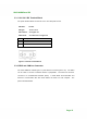
Step 1: Align the connectors. Align the RJ-45 connector on the LAN cable with one of
the RJ-45 connectors on the IOVU-430M. See Figure 3-9.
Figure 3-9: LAN Connection
Step 2: Insert the LAN cable RJ-45 connector. Once aligned, gently insert the LAN
cable RJ-45 connector into the on-board RJ-45 connector. Step 0:
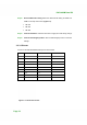
The Ethernet connector pinouts are shown below.
PIN DESCRIPTION
1 TPT+
2 TPT-
3 TPR+
4 LAN_GND
5 LAN_GND
6 TPR-
7 LAN_GND
8 LAN_GND
Table 3-6: Ethernet Connector Pinouts