
User's Manual


IOVU-430M Panel PC
Page 16
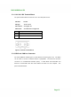
Pin Description
1 GND
2 GPIO1(95)
3 GPIO2(96)
4 GPIO3(97)
5 GPIO4(98)
6 GPIO5(99)
7 GPIO6(100)
8 CAND-/CAN_L
9 CAND+/CAN_H
10 GND
Table 3-3: GPIO and CAN Bus Connector Pinouts
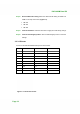
Figure 3-4: GPIO and CAN Bus Terminal Block
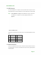
3.3.3 RS-232/422/485 Serial Port
This section outlines the usage and setup of the serial port on the bottom I/O panel.
3.3.3.1 Connecting the Serial Port
The IOVU-430M has one female DB-9 connector on the external peripheral interface
panel for connections to serial devices. Follow the steps below to connect a serial device
to the IOVU-430M.
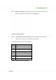
Step 1: Insert the serial connector. Insert the DB-9 connector of a serial device into
the DB-9 connector on the external peripheral interface. See Figure 3-5.