
User guide

IOPS-Q67/H61 Pluggable Module PC
Page 45
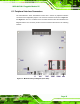
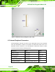
6.1 Peripheral Interface Connectors
The IOPS-Q67/H61 series’ motherboard comes with a number of peripheral interface
connectors and configuration jumpers. The connector locations are shown in Figure 6-1
and Figure 6-2. The Pin 1 locations of the on-board connectors are also indicated in the
diagrams below. The connector pinouts for these connectors are listed in the following
sections.
Figure 6-1: Main Board Layout Diagram (Front Side)