
User guide

IOPS-Q67/H61 Pluggable Module PC
Page 43
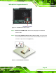
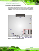
Step 3: Remove the SO-DIMM by releasing the arms on the SO-DIMM socket. (82Figure
5-5).
Figure 5-5: SO-DIMM Removal
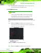
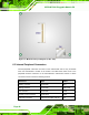
Step 4: Align the new SO-DIMM with the socket. The SO-DIMM must be oriented in
such a way that the notch in the middle of the SO-DIMM must be aligned with
the plastic bridge in the socket (
82Figure 5-6).
Step 5: Insert the SO-DIMM. Push the SO-DIMM chip into the socket at an angle
(
82Figure 5-6).
Figure 5-6: SO-DIMM Installation
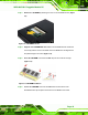
Step 6: Secure the SO-DIMM. Press the SO-DIMM down until the arms of the
SO-DIMM socket clip into place and secure the SO-DIMM in the socket.Step 0: