
User guide

IOPS-Q67/H61 Pluggable Module PC
Page 17
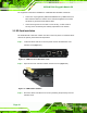
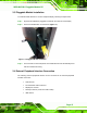
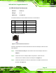
Figure 3-4: RJ-45 Ethernet Connector
The RJ-45 Ethernet connector has two status LEDs, one green and one yellow. The green
LED indicates activity on the port and the yellow LED indicates the port is linked. See
Table 3-2.
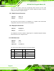
Activity/Link LED Speed LED
STATUS
DESCRIPTION STATUS DESCRIPTION
Off No link Off 10 Mbps connection
Yellow Linked Green 100 Mbps connection
Blinking TX/RX activity Orange 1 Gbps connection
Table 3-2: RJ-45 Ethernet Connector LEDs
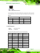
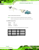
3.4.4 OPS Connector
CN Type:
80-pin JAE connector
CN Pinouts:
See
Table 3-3
The OPS connector allows connection to an OPS compliant display.
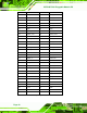
PIN NO. DESCRIPTION PIN NO. DESCRIPTION
1
DDP_3N
41
NC
2
DDP_3P
42
GND
3
GND
43
SATA_TXP
4
DDP_2N
44
SATA_TXN
5
DDP_2P
45
GND
6
GND
46
SATA_RXN
7
DDP_1N
47
SATA_RXC
8
DDP_1P
48
GND
9
GND
49
SLP_S3
10
DDP_0N
50
FANOUT