
Manual


IMBA-Q670 ATX Motherboard
Page 44
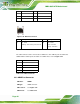
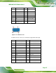
PIN DESCRIPTION PIN DESCRIPTION
3 MDIA1- 4 MDIA2-
5 MDIA2+ 6 MDIA1+
7 MDIA0- 8 MDIA0+
Table 3-23: LAN Pinouts
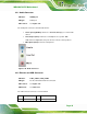
Figure 3-29: Ethernet Connector
LED Description LED Description
A on: linked
blinking: data is being sent/received
B off: 10 Mb/s
green: 100 Mb/s
orange: 1000 Mb/s
Table 3-24: Connector LEDs
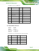
The USB connector can be connected to a USB device. The USB 2.0 ports are labeled as
USB01 and the USB 3.0 ports are labels as USB23. Please refer to
Figure 3-27.
PIN DESCRIPTION
1 5 V
2 Data-
3 Data+
4 GND
Table 3-25: USB Port Pinouts
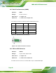
3.3.3 HDMI Port Connector
CN Label: HDMI1
CN Type:
HDMI connector
CN Location:
See Figure 3-27
CN Pinouts:
See Table 3-26