
User guide


IMBA-9454G Motherboard
Page 69
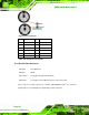
PIN Description PIN Description
1 RED 2 GREEN
3 BLUE 4 N/C
5 GND 6 GND
7 GND 8 GND
9 VCC 10 GND
11 N/C 12 DDC DAT
13 HSYNC 14 VSYNC
15 DDC CLK
Table 4-32: VGA Connector Pinouts
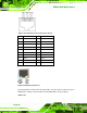
4.3.7 Serial Communications Connector
CN Label: 3IN1_DSUB1B
CN Type: D-sub 9 Male connector
CN Location: See Figure 4-25 (labeled 7)
CN Pino
uts:
See Figure 4-33 an
d Table 4-33
The serial connector on the external interface panel provides serial connection in the
RS-232 mode.
Figure 4-33: Serial Communications Connector Pinout Locations
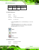
PIN DESCRIPTION
1 DATA CARRIER DETECT (DCD)
2 RECEIVE DATA (RXD)
3 TRANSMIT DATA (TXD)
4 DATA TERMINAL READY (DTR)
5 GROUND (GND)
6 DATA SET READY (DSR)
7 REQUEST TO SEND (RTS)