
User guide


IMBA-9454G Motherboard
Page 68
CN Location: See Figure 4-25 (labeled 5)
CN Pinouts: See Figure 4-31 and Table 4-31
USB devices
connect directly to the USB connectors on the external peripheral connector
panel.
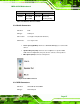
Figure 4-31: USB Connector Pinout Locations
PIN DESCRIPTION PIN DESCRIPTION
1 VCC 5 VCC
2 USBD0- 6 USBD0-
3 USBD0+ 7 USBD0+
4 GND 8 GND
Table 4-31: USB Connector Pinouts
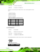
4.3.6 VGA Connector
CN Label: 3IN1_DSUB1C
CN Type: HD-D-sub 15 Female connector
CN Location: See Figure 4-25 (lab
eled 6)
CN Pinouts:
See Figure 4-32 an
d Table 4-32
The standard HD-D-sub 15 female connector connects to a CRT or LCD monitor.
Figure 4-32: VGA Connector
PIN Description PIN Description