
User guide


IMBA-9454G Motherboard
Page 66
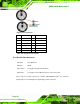
Figure 4-28: Ethernet Connector Pinout Locations
PIN DESCRIPTION PIN DESCRIPTION
1 TX+ (or MDX0+) 5 N/C (or MDX2-)
2 TX- (or MDX0-) 6 RX- (or MDX1-)
3 RX+ (or MDX1+) 7 N/C (or MDX3+)
4 N/C (or MDX2+) 8 N/C (or MDX3-)
13 MDX0+ 17 MDX2-
14 MDX0- 18 MDX1-
15 MDX1+ 19 MDX3+
16 MDX2+ 20 MDX3-
1 TX+ (or MDX0+) 5 N/C (or MDX2-)
2 TX- (or MDX0-) 6 RX- (or MDX1-)
Table 4-29: Ethernet Connector Pinouts
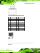
Figure 4-29: Ethernet Connector
The RJ-45 Ethernet connector has two status LEDs, one green and one yellow. The green
LED indicates activity on the port and the yellow LED indicates the port is linked
(Table 4-30).