
User guide


IMBA-9454G Motherboard
Page 47
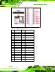
PIN DESCRIPTION PIN DESCRIPTION
27 IDE CHRDY 28 GROUND
29 IDE DACK 30 GROUND–DEFAULT
31 INTERRUPT 32 N/C
33 SA1 34 N/C
35 SA0 36 SA2
37 HDC CS0# 38 HDC CS1#
39 HDD ACTIVE# 40 GROUND
Table 4-13: IDE Connector Pinouts
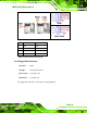
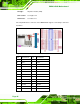
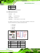
4.2.12 Infrared Interface Connector (5-pin)
CN Label:
IR1
CN Type:
5-pin header (1x5)
CN Location:
See Figure 4-13
CN Pinou
ts:
See Table 4-14
The infra
red interface connector supports both Serial Infrared (SIR) and Amplitude Shift
Key Infrared (ASKIR) interfaces.
Figure 4-13: Infrared Connector Pinout Locations
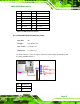
PIN DESCRIPTION
1 VCC
2 NC