Owner manual
Manuals
Brands
IEI Integration Manuals
Hardware
IMB-H612A
21
22
23
24
25
26
27
28
29
30
IMB
-
H6
1
2
Mi
c
r
o
-
A
T
X
M
ot
her
boa
r
d
Page
6
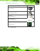
1
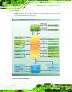
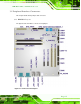
.7
D
at
a F
l
o
w
Figure
1-4
s
h
ows the da
ta flo
w between t
he s
ystem
chipset, the C
PU an
d other
components
insta
lled on th
e m
otherboard.
Figure
1-4
:
Data F
low
Diagram
1
...
...
19
20
21
22
23
...
...
199