Manual
Manuals
Brands
IEI Integration Manuals
Hardware
IMB-H610A
31
32
33
34
35
36
37
38
39
40
IMB
-
H
610 M
i
c
ro
-
A
T
X
M
ot
her
boar
d
Page
22
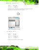
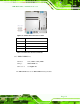
Figure
3-6
:
DDR3 DIMM
Slo
t Location
s
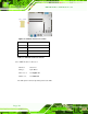
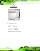
3.
2.
6
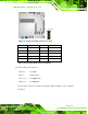
D
ebug Por
t
C
onne
ct
or
C
N
L
abel
:
TS
1
C
N Ty
p
e
:
9-
pin header
C
N
L
ocat
i
on:
See
Figure
3-7
C
N
Pi
nout
s
:
See
Ta
b
l
e
3-
6
The
debu
g por
t
co
nnector
is f
or s
ystem debug
.
1
...
...
35
36
37
38
39
...
...
192