
Instruction Manual


IBX-530B-270 Embedded System
Page 108
B.1 Peripheral Interface Connectors
NOTE:
The jumpers and connectors shown in the section below are those
jumpers and connectors that are relevant to the configuration and
installation of the embedded system.
The IBX-530B-N270 embedded system motherboard, the AFLMB-945GSE comes with a
number of peripheral interface connectors. The pinouts for the connectors that are used in
the IBX-530B-N270 are listed below:
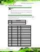
PIN NO. DESCRIPTION
1 Battery +3.3V
2 GND
TableeB-1: Battery Connector Pinouts (BT1)
Pin No. Description Pin No. Description
1 GROUND 26 CD1
2 D3 27 D11
3 D4 28 D12
4 D5 29 D13
5 D6 30 D14
6 D7 31 D15
7 CE 32 CE2
8 A10 33 VS1
9 OE 34 IOR
10 A9 35 IOW
11 A8 36 WE
12 A7 37 IRQ
13 VCC1 38 VCC
14 A6 39 CSEL
15 A5 40 VS2
16 A4 41 RESET