
Manual
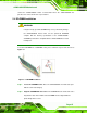
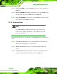
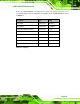
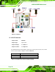
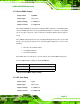
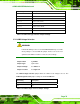
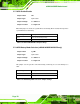
Table Of Contents
- 1 Introduction
- 2 Detailed Specifications
- 3 Unpacking
- 4 Connectors
- 4.1 Peripheral Interface Connectors
- 4.2 Internal Peripheral Connectors
- 4.2.1 BIOS Battery Connector
- 4.2.2 CompactFlash® Socket
- 4.2.3 Digital I/O Connector
- 4.2.4 Fan Connector
- 4.2.5 Front Panel Connector
- 4.2.6 IDE Connector
- 4.2.7 Infrared Interface Connector
- 4.2.8 Keyboard/Mouse Connector
- 4.2.9 LCD Backlight Inverter Connector
- 4.2.10 LED Connector
- 4.2.11 LVDS LCD Connector
- 4.2.12 MCU LAN Connector
- 4.2.13 PCIe Mini Card Slot
- 4.2.14 Power Connectors
- 4.2.15 SATA Drive Connectors
- 4.2.16 SATA Power Connectors
- 4.2.17 Serial Port Connectors (RS-232)
- 4.2.18 Serial Port Connectors (RS-422/485)
- 4.2.19 SO-DIMM Socket
- 4.2.20 SPDIF Connector
- 4.2.21 TV Out Connector
- 4.2.22 USB Connectors
- 4.3 External Peripheral Interface Connector Panel
- 5 Installation
- 6 BIOS Setup
- 7 Software Installation
- 8 Battery Monitoring
- A BIOS Options
- B Terminology
- C Digital I/O Interface
- D Watchdog Timer
- E Address Mapping
- F Hazardous Materials Disclosure

eKINO-945GSE Motherboard
Page 74
5.7.7 UPS Enable/Disable
Jumper Label: JP3
Jumper Type:
2-pin header
Jumper Settings:
See
Table 5-8
Jumper Location:
See
Figure 5-4
When this jumper is closed, the system will use the battery when needed, when open the
system will not use the battery.
Pin Setting Description
Open Don't use the battery backup
Closed Use the battery function
Table 5-8: UPS Enable/Disable Jumper Settings
5.7.8 UPS/Battery Mode Selection (eKINO-945GSE-N270UPS only)
Jumper Label: J_U/B1
Jumper Type:
3-pin header
Jumper Settings:
See
Table 5-9
Jumper Location:
See
Figure 5-4
This jumper sets the system to run off the battery exclusively, or to use the battery as a
UPS.
Pin Setting Description
1-2 UPS
2-3 Battery
Table 5-9: UPS/Battery Mode Selection Jumper Settings