
Manual
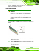
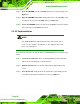
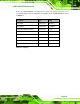
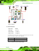
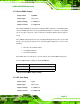
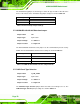
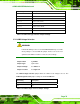
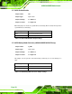
Table Of Contents
- 1 Introduction
- 2 Detailed Specifications
- 3 Unpacking
- 4 Connectors
- 4.1 Peripheral Interface Connectors
- 4.2 Internal Peripheral Connectors
- 4.2.1 BIOS Battery Connector
- 4.2.2 CompactFlash® Socket
- 4.2.3 Digital I/O Connector
- 4.2.4 Fan Connector
- 4.2.5 Front Panel Connector
- 4.2.6 IDE Connector
- 4.2.7 Infrared Interface Connector
- 4.2.8 Keyboard/Mouse Connector
- 4.2.9 LCD Backlight Inverter Connector
- 4.2.10 LED Connector
- 4.2.11 LVDS LCD Connector
- 4.2.12 MCU LAN Connector
- 4.2.13 PCIe Mini Card Slot
- 4.2.14 Power Connectors
- 4.2.15 SATA Drive Connectors
- 4.2.16 SATA Power Connectors
- 4.2.17 Serial Port Connectors (RS-232)
- 4.2.18 Serial Port Connectors (RS-422/485)
- 4.2.19 SO-DIMM Socket
- 4.2.20 SPDIF Connector
- 4.2.21 TV Out Connector
- 4.2.22 USB Connectors
- 4.3 External Peripheral Interface Connector Panel
- 5 Installation
- 6 BIOS Setup
- 7 Software Installation
- 8 Battery Monitoring
- A BIOS Options
- B Terminology
- C Digital I/O Interface
- D Watchdog Timer
- E Address Mapping
- F Hazardous Materials Disclosure
eKINO-945GSE Motherboard
Page 72
The CF Card Setup jumper sets the CF Type I card or CF Type II cards as either the slave
device or the master device. CF Card Setup jumper settings are shown in
Table 5-4.
Pin Setting Description
Open Slave
Closed Master
Table 5-4: CF Card Setup Jumper Settings
5.7.4 COM3 RS-232/422/485 Selection Jumper
Jumper Label: JP1
Jumper Type:
6-pin header
Jumper Settings:
See
Table 5-5
Jumper Location:
See
Figure 5-4
The RS-232/422/485 Serial Port Select jumper sets the communication protocol used by
COM3. The RS-232/422/485 Serial Port Select settings are shown in
Table 5-5.
Pin Setting Description
1-2 RS-232
3-4 RS-422
5-6 RS-485
Table 5-5: COM3 RS-232/422/485 Selection Jumper Pinouts
5.7.5 LCD Panel Type Selection
Jumper Label: J_LCD_TYPE1
Jumper Type:
8-pin header
Jumper Settings:
See
Table 5-7
Jumper Location:
See
Figure 5-4
The LCD Panel Type Selection jumper allows the LVDS screen voltage to be set. The
LCD Panel Type Selection jumper settings are shown in
Table 5-7.