
Manual
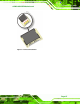
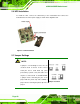
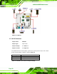
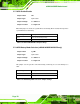
Table Of Contents
- 1 Introduction
- 2 Detailed Specifications
- 3 Unpacking
- 4 Connectors
- 4.1 Peripheral Interface Connectors
- 4.2 Internal Peripheral Connectors
- 4.2.1 BIOS Battery Connector
- 4.2.2 CompactFlash® Socket
- 4.2.3 Digital I/O Connector
- 4.2.4 Fan Connector
- 4.2.5 Front Panel Connector
- 4.2.6 IDE Connector
- 4.2.7 Infrared Interface Connector
- 4.2.8 Keyboard/Mouse Connector
- 4.2.9 LCD Backlight Inverter Connector
- 4.2.10 LED Connector
- 4.2.11 LVDS LCD Connector
- 4.2.12 MCU LAN Connector
- 4.2.13 PCIe Mini Card Slot
- 4.2.14 Power Connectors
- 4.2.15 SATA Drive Connectors
- 4.2.16 SATA Power Connectors
- 4.2.17 Serial Port Connectors (RS-232)
- 4.2.18 Serial Port Connectors (RS-422/485)
- 4.2.19 SO-DIMM Socket
- 4.2.20 SPDIF Connector
- 4.2.21 TV Out Connector
- 4.2.22 USB Connectors
- 4.3 External Peripheral Interface Connector Panel
- 5 Installation
- 6 BIOS Setup
- 7 Software Installation
- 8 Battery Monitoring
- A BIOS Options
- B Terminology
- C Digital I/O Interface
- D Watchdog Timer
- E Address Mapping
- F Hazardous Materials Disclosure
eKINO-945GSE Motherboard
Page 68
5.6 UPS Installation
To install the UPS, connect the UPS battery to the motherboard and connect the
motherboard to the 9-28 V power supply as shown in the diagram below.
Figure 5-3: UPS Installation
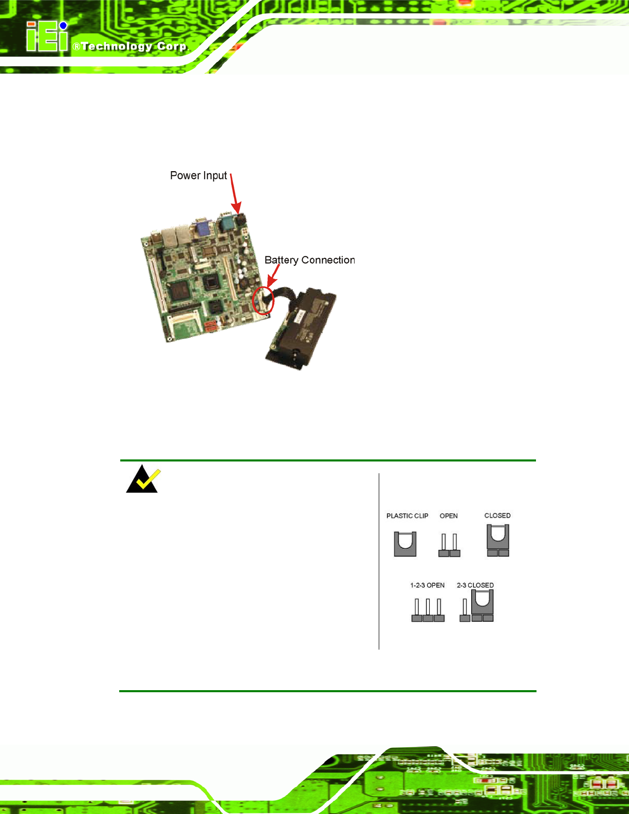
5.7 Jumper Settings
NOTE:
A jumper is a metal bridge used to close an
electrical circuit. It consists of two or three
metal pins and a small metal clip (often
protected by a plastic cover) that slides over
the pins to connect them. To CLOSE/SHORT
a jumper means connecting the pins of the
jumper with the plastic clip and to OPEN a
jumper means removing the plastic clip from a
jumper.
Jumper Locations