
Manual
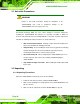
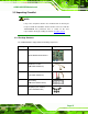
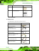
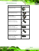
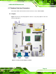
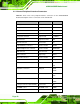
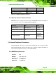
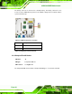
Table Of Contents
- 1 Introduction
- 2 Detailed Specifications
- 3 Unpacking
- 4 Connectors
- 4.1 Peripheral Interface Connectors
- 4.2 Internal Peripheral Connectors
- 4.2.1 BIOS Battery Connector
- 4.2.2 CompactFlash® Socket
- 4.2.3 Digital I/O Connector
- 4.2.4 Fan Connector
- 4.2.5 Front Panel Connector
- 4.2.6 IDE Connector
- 4.2.7 Infrared Interface Connector
- 4.2.8 Keyboard/Mouse Connector
- 4.2.9 LCD Backlight Inverter Connector
- 4.2.10 LED Connector
- 4.2.11 LVDS LCD Connector
- 4.2.12 MCU LAN Connector
- 4.2.13 PCIe Mini Card Slot
- 4.2.14 Power Connectors
- 4.2.15 SATA Drive Connectors
- 4.2.16 SATA Power Connectors
- 4.2.17 Serial Port Connectors (RS-232)
- 4.2.18 Serial Port Connectors (RS-422/485)
- 4.2.19 SO-DIMM Socket
- 4.2.20 SPDIF Connector
- 4.2.21 TV Out Connector
- 4.2.22 USB Connectors
- 4.3 External Peripheral Interface Connector Panel
- 5 Installation
- 6 BIOS Setup
- 7 Software Installation
- 8 Battery Monitoring
- A BIOS Options
- B Terminology
- C Digital I/O Interface
- D Watchdog Timer
- E Address Mapping
- F Hazardous Materials Disclosure

eKINO-945GSE Motherboard
Page 28
Quantity Item and Part Number Image
1 Utility CD
1 Quick Installation Guide
Table 3-1: Packing List
3.3.2 Optional Items
The eKINO-945GSE is shipped with the following components:
Item and Part Number Image
HDD cable
(P/N: 32200-000009-RS)
HDTV cable set
(P/N: HDTVCABLESET-01)
Dual USB cable (w bracket)
(P/N: CB-USB02-RS)
4-pin power to terminal block cable
(P/N: 32100-192900-RS)
RS-232 cable with bracket
(P/N: 19800-000300-100-RS)
RS-422/485 cable with bracket
(P/N: 32200-833600-RS)