
Manual
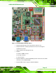


Table Of Contents
- 1 Introduction
- 2 Detailed Specifications
- 3 Unpacking
- 4 Connectors
- 4.1 Peripheral Interface Connectors
- 4.2 Internal Peripheral Connectors
- 4.2.1 BIOS Battery Connector
- 4.2.2 CompactFlash® Socket
- 4.2.3 Digital I/O Connector
- 4.2.4 Fan Connector
- 4.2.5 Front Panel Connector
- 4.2.6 IDE Connector
- 4.2.7 Infrared Interface Connector
- 4.2.8 Keyboard/Mouse Connector
- 4.2.9 LCD Backlight Inverter Connector
- 4.2.10 LED Connector
- 4.2.11 LVDS LCD Connector
- 4.2.12 MCU LAN Connector
- 4.2.13 PCIe Mini Card Slot
- 4.2.14 Power Connectors
- 4.2.15 SATA Drive Connectors
- 4.2.16 SATA Power Connectors
- 4.2.17 Serial Port Connectors (RS-232)
- 4.2.18 Serial Port Connectors (RS-422/485)
- 4.2.19 SO-DIMM Socket
- 4.2.20 SPDIF Connector
- 4.2.21 TV Out Connector
- 4.2.22 USB Connectors
- 4.3 External Peripheral Interface Connector Panel
- 5 Installation
- 6 BIOS Setup
- 7 Software Installation
- 8 Battery Monitoring
- A BIOS Options
- B Terminology
- C Digital I/O Interface
- D Watchdog Timer
- E Address Mapping
- F Hazardous Materials Disclosure
eKINO-945GSE Motherboard
Page 15
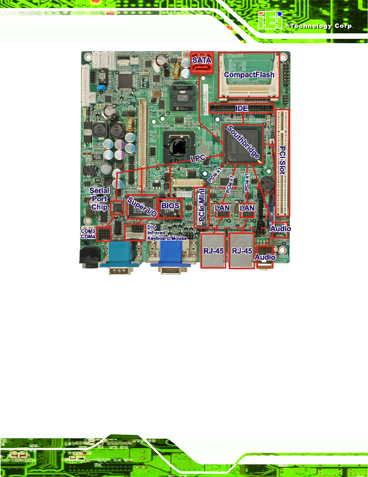
Figure 2-5: Intel® ICH7M Southbridge Chipset
Complies with PCI Express Base Specification, Revision 1.0a
Complies with PCI Local Bus Specification, Revision 2.3 and supports
33 MHz PCI operations
Supports ACPI Power Management Logic
Contains:
o Enhanced DMA controller
o Interrupt controller
o Timer functions
Integrated SATA host controller with DMA operations interfaced to two SATA
connectors on the eKINO-945GSE
Integrated IDE controller supports Ultra ATA 100/66/33