
Manual
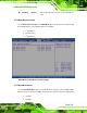
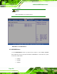


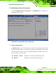


Table Of Contents
- 1 Introduction
- 2 Detailed Specifications
- 3 Unpacking
- 4 Connectors
- 4.1 Peripheral Interface Connectors
- 4.2 Internal Peripheral Connectors
- 4.2.1 BIOS Battery Connector
- 4.2.2 CompactFlash® Socket
- 4.2.3 Digital I/O Connector
- 4.2.4 Fan Connector
- 4.2.5 Front Panel Connector
- 4.2.6 IDE Connector
- 4.2.7 Infrared Interface Connector
- 4.2.8 Keyboard/Mouse Connector
- 4.2.9 LCD Backlight Inverter Connector
- 4.2.10 LED Connector
- 4.2.11 LVDS LCD Connector
- 4.2.12 MCU LAN Connector
- 4.2.13 PCIe Mini Card Slot
- 4.2.14 Power Connectors
- 4.2.15 SATA Drive Connectors
- 4.2.16 SATA Power Connectors
- 4.2.17 Serial Port Connectors (RS-232)
- 4.2.18 Serial Port Connectors (RS-422/485)
- 4.2.19 SO-DIMM Socket
- 4.2.20 SPDIF Connector
- 4.2.21 TV Out Connector
- 4.2.22 USB Connectors
- 4.3 External Peripheral Interface Connector Panel
- 5 Installation
- 6 BIOS Setup
- 7 Software Installation
- 8 Battery Monitoring
- A BIOS Options
- B Terminology
- C Digital I/O Interface
- D Watchdog Timer
- E Address Mapping
- F Hazardous Materials Disclosure

eKINO-945GSE Motherboard
Page 125
Î
Enabled DEFAULT
Can be booted from a remote system through the
LAN
6.5.2 Boot Device Priority
Use the Boot Device Priority menu (9BIOS Menu 16) to specify the boot sequence from
the available devices. The following options are available:
1
st
Boot Device
2
nd
Boot Device
3
rd
Boot Device
BIOS Menu 16: Boot Device Priority Settings
6.5.3 Hard Disk Drives
Use the Hard Disk Drives menu to specify the boot sequence of the available HDDs.
When the menu is opened, the HDDs connected to the system are listed as shown below:
1st Drive
2nd Drive