
Owner manual

eKINO-945GSE Motherboard
Page 57
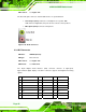
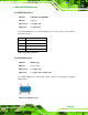
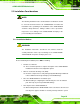
Pin
Signal Name
Pin
Signal Name
Pin
Signal Name
8
Analog vertical sync
16
GND
24
TMDS Clock -
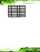
C1
Analog Red
--
--
--
--
C2
Analog Green
--
--
--
--
C3
Analog Blue
--
--
--
--
C4
Analog Horizontal Sync
--
--
--
--
C5
Analog GND
--
--
--
--
Table 4-20: DVI Connector Pinouts
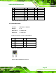
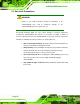
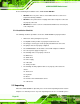
4.3.3 LAN Connectors
CN Label: LAN/USB1 & LAN/USB2
CN Type:
RJ-45
CN Location:
See
8Figure 4-24
CN Pinouts:
See
8Table 4-21
The RJ-45 connectors connect to a wired network.
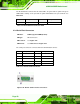
Pin Description Pin Description
1 MDIA3- 5 MDIA1+
2 MDIA3+ 6 MDIA2+
3 MDIA2- 7 MDIA0-
4 MDIA1- 8 MDIA0+
Table 4-21: LAN Pinouts
Figure 4-26: RJ-45 Ethernet Connector