
Manual


ECW-281B/281B2-R30/N270 Embedded System
Page 27
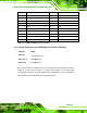
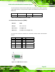
41 N/C 42 N/C
43 N/C 44 RF_LINK#
45 N/C 46 BLUELED#
47 N/C 48 1.5V
49 N/C 50 GND
51 N/C 52 VCC3
Table 3-7: PCIe Mini Card Slot Pinouts
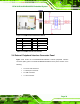
3.3.7 Power Button Connector
CN Label:
PWRBTN1
CN Type:
2-pin wafer (1x2)
CN Location:
See
77Figure 3-8
CN Pinouts:
See
77Table 3-8
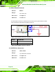
The power button connector is connected to a power switch on the system chassis to
enable users to turn the system on and off.
Figure 3-8: Power Button Connector Location
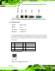
PIN NO. DESCRIPTION
1 Power Switch
2 GND
Table 3-8: Power Button Connector Pinouts