
Manual

ECW-281B-R21/N270 Embedded System
Page 21
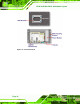
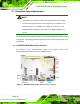
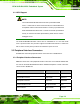
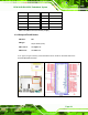
Figure 3-2: ATX Power Connector Location
PIN NO. DESCRIPTION
1 +12V
2 GND
3 GND
4 +5V
Table 3-2: ATX Power Connector Pinouts
3.3.2 ATX Power Supply Enable Connector
CN Label:
ATXCTL1
CN Type:
3-pin wafer (1x3)
CN Location:
See
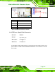
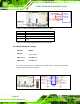
701H701H703HFigure 3-3
CN Pinouts:
See
702H702H704HTable 3-3
The ATX power supply enable connector is connected to the ATX mode connector on the
power module to enable the ECW-281B/281B2-R21/N270 to be connected to an ATX
power supply.