
User guide
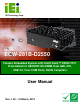

ECW-281B-D2550 Embedded System
Page vii
5.3.6.1 Serial Port n Configuration....................................................................... 59
5.3.7 F81866 H/W Monitor....................................................................................... 65
5.3.7.1 Smart Fan Mode Configuration ................................................................ 66
5.3.8 Serial Port Console Redirection ...................................................................... 66
5.3.9 iEi Feature ....................................................................................................... 69
5.4 CHIPSET ................................................................................................................... 70
5.4.1 Host Bridge Configuration .............................................................................. 71
5.4.1.1 Intel IGD Configuration............................................................................ 71
5.4.2 South Bridge Configuration............................................................................. 72
5.5 BOOT........................................................................................................................ 74
5.6 SECURITY................................................................................................................. 76
5.7 SAV E & EXIT ............................................................................................................ 76
6 INTERFACE CONNECTORS................................................................................... 78
6.1 PERIPHERAL INTERFACE CONNECTORS..................................................................... 79
6.2 INTERNAL PERIPHERAL CONNECTORS ...................................................................... 80
6.2.1 5 V SATA Power Connectors (SATA_PWR1, SATA_PWR2) ............................ 81
6.2.2 12 V Power Connector (CN3).......................................................................... 81
6.2.3 Audio Connector (AUDIO1)............................................................................. 81
6.2.4 Backlight Inverter Connectors (INV1, INV2) .................................................. 82
6.2.5 Battery Connector (CN1)................................................................................. 82
6.2.6 Digital I/O Connector (DIO1) ......................................................................... 82
6.2.7 Fan Connectors (CPU_FAN1, SYS_FAN1)...................................................... 83
6.2.8 Keyboard/Mouse Connector (KB_MS1) .......................................................... 83
6.2.9 LVDS1 Connector (LVDS1) ............................................................................. 83
6.2.10 LVDS2 Connector (LVDS2) ........................................................................... 84
6.2.11 PCIe Mini Card Slots (M_PCIE1, M_PCIE2)............................................... 84
6.2.12 Power & HDD LED Connector (CN2).......................................................... 85
6.2.13 Power Button Connector (PWR_BTN1) ........................................................ 86
6.2.14 Reset Button Connector (RST_BTN1)............................................................ 86
6.2.15 RS-232 Serial Port Connectors (COM2, COM3) .......................................... 86
6.2.16 RS-422/485 Serial Port Connector (COM4).................................................. 86
6.2.17 SATA Drive Connectors (SATA1, SATA2) ...................................................... 87
6.2.18 USB Connectors (USB2, USB3) .................................................................... 87
6.3 EXTERNAL INTERFACE PANEL CONNECTORS ............................................................ 87