
User guide

ECW-281B-D2550 Embedded System
Page 41
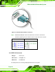
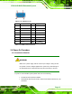
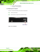
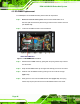
Figure 3-33: VGA Connector
Pin Description Pin Description
1 RED 2 GREEN
3 BLUE 4 NC
5 GND 6 GND
7 GND 8 GND
9 VCC 10 GND
11 NC 12 DDC DAT
13 HSYNC 14 VSYNC
15 DDCCLK
Table 3-10: VGA Connector Pinouts
3.9 Power-On Procedure
3.9.1 Installation Checklist
WARNING:
Make sure a power supply with the correct input voltage is being fed into
the system. Incorrect voltages applied to the system may cause damage to
the internal electronic components and may also cause injury to the user.
To power on the embedded system please make sure of the following:
The bottom surface panel is installed
All peripheral devices (VGA monitor, serial communications devices etc.) are
connected