
User guide


ECW-281B-D2550 Embedded System
Page 39
Step 1: Locate the USB connectors. The locations of the USB connectors are shown
in
Figure 1-3.
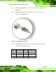
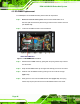
Step 2: Align the connectors. Align the USB device connector with one of the
connectors. See
Figure 3-31.
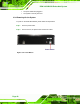
Figure 3-31: USB Device Connection
Step 3: Insert the device connector. Once aligned, gently insert the USB device
connector into the on-board connector.
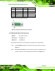
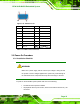
Pin Description Pin Description
1 VCC 5 VCC
2 DATA- 6 DATA-
3 DATA+ 7 DATA+
4 GROUND 8 GROUND
Table 3-9: USB 2.0 Port Pinouts