
User guide

ECW-281B-D2550 Embedded System
Page 89
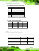
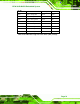
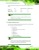
6.3.4 VGA Connector (VGA1)
PIN NO. DESCRIPTION PIN NO. DESCRIPTION
1 RED 2 GREEN
3 BLUE 4 NC
5 GND 6 GND
7 GND 8 GND
9 VCC 10 GND
11 NC 12 DDC DAT
13 HSYNC 14 VSYNC
15 DDCCLK
Table 6-24: VGA Connector (VGA1) Pinouts
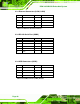
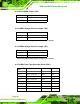
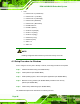
6.4 Jumper Settings
The table below lists the jumpers on the ECW-281B-D2550 motherboard.
Jumper Name Label Type
AT/ATX power selection JP2 2-pin header
Clear CMOS JP3 3-pin header
LVDS1 voltage selection JP4 3-pin header
LVDS2 voltage selection JP1 3-pin header
LVDS2 panel type selection SW1 DIP switch
Table 6-25: Jumpers
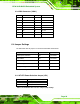
6.4.1 AT/ATX Power Selection Jumper (JP2)
Pin Description
Short 1-2 Use ATX power (Default)
Off Use AT power
Table 6-26: AT/ATX Power Selection Jumper (JP2) Settings