
User guide

ECW-281B-D2550 Embedded System
Page 87
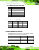
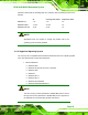
6.2.17 SATA Drive Connectors (SATA1, SATA2)
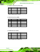
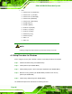
6.2.18 USB Connectors (USB2, USB3)
PIN NO. DESCRIPTION PIN NO. DESCRIPTION
1 USB_VCC 2 GND
3 DATA- 4 DATA+
5 DATA+ 6 DATA-
7 GND 8 USB_VCC
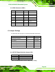
6.3 External Interface Panel Connectors
The table below lists the rear panel connectors on the ECW-281B-D2550 motherboard.
Pinouts of these connectors can be found in the following sections.
Connector Type Label
Dual USB port Dual USB port USB1
Ethernet connectors RJ-45 LAN1, LAN2
RS-232 serial port connector Male DB-9 COM1
VGA connector 15-pin female VGA1
Table 6-20: Rear Panel Connectors
PIN NO. DESCRIPTION
1 GND
2
TX+
3
TX-
4 GND
5
RX-
6
RX+
7 GND
Table 6-18: SATA Drive Connector (SATA1, SATA2) Pinouts
Table 6-19: USB Connectors (USB2, USB3) Pinouts