
Manual


ECN-360A-HM65 Embedded System
Page 45
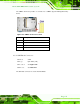
4.3.1 Ethernet Connectors
CN Label: LAN1 and LAN2
CN Type:
RJ-45
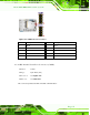
CN Location: See Figure 4-20
CN Pinouts: See Table 4-22
The motherboard is equipped with two built-in RJ-45 Ethernet controllers. The controllers
can connect to the LAN through two RJ-45 LAN connectors. There are two LEDs on the
connector indicating the status of LAN. The pin assignments are listed in the following
table:
Pin Description Pin Description
1 LAN1_MDI0+ 7 LAN1_MDI2+
2 LAN1_MDI0- 8 LAN1_MDI2-
3. LAN1_MDI1+ 9 LAN1_MDI3+
4. LAN1_MDI1- 10 LAN1_MDI3-
Table 4-22: LAN Pinouts
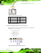
Figure 4-21: RJ-45 Ethernet Connector
The RJ-45 Ethernet connector has two status LEDs, one yellow (activity/link) and one
green/orange (speed). The yellow LED indicates activity/link on the port and the
green/orange LED indicates the connection speed. See Table 4-23.
ACT/LINK LED SPEED LED
STATUS
DESCRIPTION STATUS DESCRIPTION
OFF No Link OFF 10 Mbps connection
YELLOW Link GREEN 100 Mbps connection
BLINKING Data activity ORANGE 1000 Mbps connection
Table 4-23: RJ-45 Ethernet Connector LEDs