
Manual


ECN-360A-HM65 Embedded System
Page 44
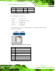
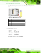
Figure 4-19: SPI Flash Connector Location
Pin Description Pin Description
1
+V3.3M_SPI_CON
5
SPI_SI_SW
2
SPI_CS
6
GND
3
SPI_SO_SW
7
GND
4
SPI_CLK_SW
8
GND
Table 4-21: SPI Flash Connector
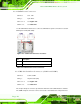
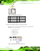
4.3 External Peripheral Interface Connector Panel
Figure 4-20 shows the motherboard external peripheral interface connector (EPIC) panel.
The EPIC panel consists of the following:
2 x RJ-45 LAN connectors
2 x HDMI connectors
2 x USB 2.0 connectors
2 x USB 3.0 connectors
1 x VGA connector
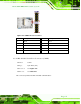
Figure 4-20: External Peripheral Interface Connectors