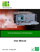
EC-1040GB Rackmount Workstation IEI Technology Corp. MODEL: EC-1040GB 4U 14-slot Rackmount LCD Workstation User Manual Page i Rev. 3.
EC-1040GB Rackmount Workstation Revision Date Version Changes 18 July, 2011 3.00 Updated for R30 version December, 2006 1.
EC-1040GB Rackmount Workstation Copyright COPYRIGHT NOTICE The information in this document is subject to change without prior notice in order to improve reliability, design and function and does not represent a commitment on the part of the manufacturer. In no event will the manufacturer be liable for direct, indirect, special, incidental, or consequential damages arising out of the use or inability to use the product or documentation, even if advised of the possibility of such damages.
EC-1040GB Rackmount Workstation Packing List NOTE: If any of the components listed in the checklist below are missing, please do not proceed with the installation. Contact the IEI reseller or vendor you purchased the EC-104G Rackmount Workstation from or contact an IEI sales representative directly. To contact an IEI sales representative, please send an email to sales@iei.com.tw. The items listed below should all be included in the EC-104G Rackmount Workstation package.
EC-1040GB Rackmount Workstation Table of Contents 1 INTRODUCTION........................................................................................................... 1 1.1 EC-1040GB OVERVIEW ............................................................................................. 2 1.2 EC-1040GB FEATURES .............................................................................................. 2 1.3 MODEL VARIATIONS .............................................................................
EC-1040GB Rackmount Workstation 4.2.2 Unpacking Procedure ...................................................................................... 20 4.2.3 Packing List ..................................................................................................... 21 4.3 PRE-INSTALLATION PREPARATION ............................................................................ 23 4.3.1 System Planning............................................................................................... 23 4.3.
EC-1040GB Rackmount Workstation 5.7 DISK DRIVE REPLACEMENT ..................................................................................... 57 5.7.1 3.5” Disk Drive Replacement .......................................................................... 57 5.7.2 5.25” Disk Drive Replacement ........................................................................ 58 6 ON SCREEN DISPLAY (OSD) CONTROLS .............................................................. 59 6.1 USER MODE OSD STRUCTURE ............
EC-1040GB Rackmount Workstation List of Figures Figure 2-1: EC-1040GB Front Panel..............................................................................................6 Figure 2-2: EC-1040GB 14 Slot Rear Panel ..................................................................................7 Figure 2-3: EC-1040GB Motherboard Rear Panel........................................................................8 Figure 2-4: EC-1040GB Top Panel ...........................................................
EC-1040GB Rackmount Workstation Figure 5-3: PSU Mounting Bracket Retention Screws ..............................................................54 Figure 5-4: Cooling Fan Spring Clips .........................................................................................56 Figure 6-1: OSD Control Buttons ................................................................................................60 Figure 6-2: Main Menu....................................................................................
EC-1040GB Rackmount Workstation List of Tables Table 1-1: EC-1040GB Model Variations ......................................................................................3 Table 2-1: General Physical Dimensions ...................................................................................10 Table 3-1: EC-1040GB Specifications.........................................................................................14 Table 3-2: LCD Specifications ........................................................
EC-1040GB Rackmount Workstation Chapter 1 1 Introduction Page 1
EC-1040GB Workstation 1.1 EC-1040GB Overview The EC-1040GB is a PC/AT compatible computer designed for industrial applications. It has a rugged steel chassis specially designed to work under harsh environmental conditions while also being high reliability. The EC-1040GB features 14-slot passive backplanes and a full line of dependable AC/DC power supplies. The EC-1040GB can withstand shock, vibration, dust and a wide range of temperatures in industrial environments.
EC-1040GB Workstation 300W Touch ATX Motherboard Screen Rear Panel EC-1040GBB/A130A-R30 No No Yes 14 EC-1040GBB/A130A/R-R30 Yes No Yes 14 EC-1040GBBATX/A130A-R30 No Yes Yes 7 EC-1040GBBATX/A130A/R-R30 Yes Yes Yes 7 Power Supply Expansion Slots Table 1-1: EC-1040GB Model Variations 1.
EC-1040GB Workstation 1.5 Certifications All EC-1040GB rackmount workstations comply with the following international standards: RoHS For a more detailed description of this standard, please refer to Appendix A.
EC-1040GB Workstation Chapter 2 2 Mechanical Overview Page 5
EC-1040GB Workstation 2.1 External Overview The following sections describe the physical layout of the EC-1040GB rackmount workstation. 2.1.1 Front Panel The EC-1040GB rackmount workstation has the following front panel items: Plastic frame 6.5” Flat panel TFT LCD screen with OSD controls Lockable drive bay access door conceals o o o Three 5.25” drive bays One 3.
EC-1040GB Workstation 2.1.
EC-1040GB Workstation 2.1.
EC-1040GB Workstation 2.1.
EC-1040GB Workstation 2.1.5 Left Side Panel The EC-1040GB rackmount workstation has the following left side panel items: Cooling vents Figure 2-5: EC-1040GB Left Side Panel 2.2 Physical Dimensions The following sections describe the physical dimensions of the EC-1040GB. 2.2.1 General Physical Dimensions General physical dimensions for the EC-1040GB are shown in Table 2-1.
EC-1040GB Workstation 2.2.2 EC-1040GB Physical Dimensions The physical dimensions of the EC-1040GB are shown in Figure 2-1.
EC-1040GB Workstation 2.2.3 Optional Keyboard Figure 2.7 shows the optional keyboard for the EC-1040GB rackmount workstation. Refer to Section 4-5-13 for installation details.
EC-1040GB Workstation Chapter 3 3 Detailed Specifications Page 13
EC-1040GB Workstation 3.1 EC-1040GB Specifications Table 3-1 shows the EC-1040GB specifications. LCD Type 6.5" TFT Input Interface VGA Max.
EC-1040GB Workstation 3.2 LCD Specifications Table 3-2 lists the EC-1040GB LCD specifications. Size 6.5” MFR/Model AUO/G065VN01 V2 Resolution VGA (640 x 480) Active Area (mm) 132.52 x 98.64 Pixel Pitch (mm) 0.207 Number of Colors 262K View Angle (H/V) 160° / 140° Brightness (cd/m2) 800 Contrast Ratio 600:1 Response Time (ms) (at 25C) 25 Power Consumption (W) 3.86 Interface LVDS Supply Voltage (V) 3.
EC-1040GB Workstation 3.3 ACE-832AP PSU Specifications Table 3-3 lists the ACE-A130A-R10 power supply specifications. INPUT Voltage 90 ~ 264 VAC Full Range Frequency 47 ~ 63 Hz Input Current 6A (RMS) @ 115 VAC 3A (RMS) @ 230 VAC Inrush Current 60 A Max for 115 VAC 90 A Max for 230 VAC OUTPUT Voltage Min. load Max. load Ripple & Noise +3.3V 0.1 A 28 A 50 mV +5V 0.2 A 30 A 50 mV +12V1 0.1 A 15 A 120 mV +12V2 0.5 A 0.3 A 120 mV -12V 0A 0.
EC-1040GB Workstation 3.4 Recommended IEI Backplanes, Motherboards and PSUs Refer to Appendix B for recommended IEI backplanes, motherboards and power supply units for the EC-1040GB rackmount workstation.
EC-1040GB Workstation Chapter 4 4 Installation Page 18
EC-1040GB Workstation 4.1 Installation Considerations 4.1.1 Installation Precautions When installing the EC-1040GB, please follow the precautions listed below: Read the user manual: The user manual provides a complete description of the EC-1040GB rackmount workstation, installation instructions and configuration options. Turn Off Power: When installing the EC-1040GB rackmount workstation, make sure the power is off.
EC-1040GB Workstation EC-1040GB rackmount workstation is separately purchased. Disk Drives: Disk drives installed into the EC-1040GB rackmount workstation are separately purchased. Disk drive support is CPU card dependent. Before purchasing a CPU card or disk drives, please check the CPU card disk drive support. 4.2 Unpacking 4.2.1 Packaging When shipped, the EC-1040GB rackmount workstation is wrapped in a plastic bag.
EC-1040GB Workstation Step 3: Use box cutters, a knife or a sharp pair of scissors to open the top of the internal (first) box. Step 4: Lift the workstation out of the boxes. Step 5: Remove both polystyrene ends from each side. Step 6: Pull the plastic cover off the workstation. Step 7: Make sure all the components listed in the packing list are present. Step 0: 4.2.3 Packing List NOTE: If some of the components listed in the checklist below are missing, please do not proceed with the installation.
EC-1040GB Workstation Quantity Description Image 2 Handle bracket 1 Power cable 2 PS/2 Keyboard/Mouse cable 1 Screw kit 1 Utility CD 1 VGA cable For Touch Panel (T-R) Models only 1 Page 22 RS-232 cable
EC-1040GB Workstation Quantity Description 1 Image Touch pen Table 4-1: Packing List 4.3 Pre-installation Preparation 4.3.1 System Planning User supplied CPU cards and backplanes or motherboards need to be installed in the system before installing the EC-1040GB rackmount workstation.
EC-1040GB Workstation screen should be placed face down on a soft working mat. 4.4 Installation Procedures 4.4.1 Preinstalled Components The following components are preinstalled in the EC-1040GB rackmount workstation. Power supply unit (PSU) Cooling fan modules Drive brackets LCD screen 4.4.
EC-1040GB Workstation Step 8: Install the PCI or ISA expansion cards (optional). Step 9: Connect all required cables. Step 10: Reinstall the CPU card clamp. Step 11: Close the top cover. Step 12: Install the keyboard (optional). Step 13: Mount the workstation.Step 0: 4.5 Installing Components into the EC-1040GB NOTE: This section gives a generic description of the component installation process for the EC-1040GB rackmount workstation.
EC-1040GB Workstation Figure 4-1: Top Cover Left Side Retention Screws (Right Side Similar) Step 2: Remove the top cover from the chassis to reveal the internal components.
EC-1040GB Workstation 4.5.2 Remove the CPU Card Clamp The CPU card clamp is secured to the EC-1040GB rackmount workstation with four retention screws. To remove the CPU card clamp, please follow the steps below. Step 1: Remove four retention screws that secure the CPU card clamp to the chassis (Figure 4-3). Figure 4-3: CPU Card Clamp Retention Screws Step 1: Remove the CPU card clamp from the chassis.Step 0: 4.5.
EC-1040GB Workstation Step 1: Remove four retention screws that secure the drive bracket to the chassis (Figure 4-4). Figure 4-4: Drive Bracket Retention Screws Step 2: Remove the drive bracket from the chassis.Step 0: 4.5.4 Remove the Drive Slot Blank Plate The drive bracket has three 5.25” and one 3.5” drive slot blank plates. To remove the drive slot blank plates, please follow the steps below. Step 1: Remove the retention screws that secure the drive slot blank plate to the drive bracket (Figure 4-5).
EC-1040GB Workstation Figure 4-5: Drive Slot Blank Plate Retention Screws Step 2: Remove the drive slot blank plate from the drive bracket.Step 0: 4.5.5 Remove the 3.5” Drive Bracket In order to access all the 5.25” drive bay retention screw holes, it is necessary to remove the 3.5” drive bracket. To remove the 3.5” drive bracket, please follow the steps below. Step 1: Remove the drive bracket from the EC-1040GB rackmount workstation (see Section 4.5.3).
EC-1040GB Workstation Figure 4-6: 3.5” Drive Bracket Retention Screws Step 3: Remove the 3.5” drive bracket from the 5.25” drive bracket.Step 0: 4.5.6 Install Drives 4.5.6.1 5.25” Disk Drive The drive bracket supports three 5.25” disk drives. To install a 5.25” disk drive, follow the instructions below. Step 1: Remove the drive bracket from the EC-1040GB rackmount workstation (see Section 4.5.3). Step 2: Remove the 3.5” drive bracket from the 5.25” drive bracket (see Section 4.5.5).
EC-1040GB Workstation Step 5: Insert the appropriate number of retention screws into each side of the 5.25” disk drive through the drive bracket (Figure 4-7). Figure 4-7: 5.25” Disk Drive Retention Screws (Other Side Similar) 4.5.6.2 3.5” Disk Drive in a 5.25” Slot With the use of IEI’s 3.5” to 5.25” drive bay rack, a standard 3.5” disk drive can be installed into a 5.25” drive bay slot. To install a 3.5” hard disk drive into a 5.25” slot of the drive bracket, follow the instructions below.
EC-1040GB Workstation Figure 4-8: 3.5” to 5.25” Drive Bay Rack Retention Screws Step 3: Remove the drive bracket from the EC-1040GB rackmount workstation (see Section 4.5.3). Step 4: Remove the 3.5” drive bracket from the 5.25” drive bracket (see Section 4.5.5). Step 5: Install the 3.5” to 5.25” drive bay rack into the drive bracket (see Section 4.5.6) Step 0: 4.5.6.3 3.5” Disk Drive To install a 3.5” disk drive, follow the instructions below.
EC-1040GB Workstation Figure 4-9: 3.5” Disk Drive Retention Screws 4.5.7 Reinstall the Drive Brackets After the drives have been installed, reinstall the drive brackets into the chassis. NOTE: It might be easier to connect the disk drive IDE/SATA connectors to the ribbon cables and the disk drive power connectors to the PSU before the drive brackets are reinstalled into the chassis. Step 1: Remount the drive brackets in the original position they were removed from.
EC-1040GB Workstation (Figure 4-10). NOTE: The backplane shown in Figure 4-10 is an example for reference only. The location and number of copper pillars depends on the backplane being used.
EC-1040GB Workstation Step 2: Mount the backplane into the chassis. Make sure the backplane is positioned so that when the CPU card and PCI/ISA expansion cards are installed, both the CPU card and the PCI/ISA card I/O connectors face the I/O brackets on the rear panel. Step 3: Align the retention screw holes in the backplane with the copper pillars installed in Step 1.
EC-1040GB Workstation 4.5.9 Install the CPU Card CAUTION Before a CPU card is inserted into the backplane, make sure the CPU card has been correctly prepared and that all the CPU card jumper settings are configured correctly. For CPU card component installation procedures, please refer to the user manual that came with the CPU card.
EC-1040GB Workstation Figure 4-12: Slot Cover Retention Screw Step 2: Remove the CPU card clamp. (See Section 4.5.2) Step 3: Slide the CPU card into the reserved PCI/ISA socket on the backplane. Make sure the back edge of the CPU card slides into the plastic guide rails at the front end of the chassis.
EC-1040GB Workstation Figure 4-13: Install the CPU Card Step 4: To secure the CPU card, reinsert the previously removed slot cover retention screw. Step 5: If a PCI/ISA expansion card is not being installed, reinstall the hold down clamp. If a PCI/ISA expansion card is being installed, proceed to the next section.Step 0: 4.5.10 Install the PCI/ISA Expansion Card To install a PCI expansion card or an ISA expansion card please follow the instructions below.
EC-1040GB Workstation Step 2: If necessary, remove the CPU card clamp. (See Section 4.5.2) Step 3: Slide the PCI/ISA expansion card into the reserved PCI/ISA socket on the backplane. Step 4: To secure the PCI/ISA expansion card, reinsert the previously removed slot cover retention screw and reinstall the hold down bar. Step 0: 4.5.
EC-1040GB Workstation 4.5.13 Install Optional Keyboard To install the optional keyboard, please follow the steps below. Step 1: Remove the cover from the keyboard bay. Step 2: Insert the keyboard slide rails into the keyboard bay while carefully routing the PS/2 connector along the bottom panel of the workstation to the internal PS/2 keyboard connector until the entire keyboard assembly locks into place. Step 3: Connect the keyboard PS/2 connector to the internal PS/2 connector (Figure 4-14).
EC-1040GB Workstation Step 4: Insert four retention screws, two each on the left and right side panels, to secure the keyboard to the workstation (Figure 4-15). Step 0: Figure 4-15: Keyboard Retention Screws 4.6 Mounting the EC-1040GB Rackmount Workstation The EC-1040GB workstation can be mounted to the posts of a standard 19” rack cabinet. Adequate rails, rack tray, or side brackets should also be available for supporting the weight of the workstation.
EC-1040GB Workstation To rack mount the workstation, please follow the steps below. Step 1: The left and right side panels of the workstation each have four screw holes for rack handle bracket installation. Assemble the rack handle brackets and secure them to the workstation.
EC-1040GB Workstation Step 2: Remove the rack slides from the rack slide brackets.
EC-1040GB Workstation Step 3: The left and right side panels of the workstation each have five screw holes for rack slides. Attach one slide section each to the left and right side panel of the workstation.
EC-1040GB Workstation Step 4: Assemble the slide brackets per the manufacturer’s instructions.
EC-1040GB Workstation Step 5: Attach the slide brackets to the rack per the manufacturer’s instructions.
EC-1040GB Workstation Step 6: Insert the workstation with the attached slides into the rack slide brackets until the handle brackets are flush against the rack. (See Figure 4-21) Figure 4-21: Install Workstation into Rack Step 7: If necessary, secure the workstation handle brackets to the rack with the fasteners that came with the workstation.
EC-1040GB Workstation Chapter 5 5 Maintenance Page 48
EC-1040GB Workstation 5.1 Maintenance Overview Maintaining the EC-1040GB rackmount workstation is essential for the smooth operating of system applications. Maintaining the system might mean replacing failed components during the lifetime of the workstation. The following EC-1040GB components can be replaced. CPU card PCI/ISA expansion card Backplane Power supply unit (PSU) Cooling fans Disk drives o o 3.5” 5.
EC-1040GB Workstation 5.2 CPU Card Replacement To replace a CPU card, please follow the instructions below. Step 1: Turn off and disconnect the workstation from all power sources. Step 2: Remove the workstation from the rack in which it is installed. Step 3: Open the top cover of the EC-1040GB rackmount workstation. (See Section 4.5.1) Step 4: Disconnect all internal and external peripheral device connections from the CPU card. Step 5: Remove the CPU card clamp. (See Section 4.5.
EC-1040GB Workstation Step 4: Disconnect all internal and external peripheral device connections from the PCI/ISA expansion card. Step 5: Remove the CPU card clamp. (See Section 4.5.2) Step 6: Remove the retention screw that secures the PCI/ISA expansion card to the slot on the rear panel. Step 7: Slide the PCI/ISA expansion card out of the workstation. Step 8: Install a new PCI/ISA expansion card. (See Section 4.5.9) Step 9: Reinstall the CPU card clamp. Step 10: Reinstall the top cover of the workstation.
EC-1040GB Workstation Step 8: Reinstall and reconnect all CPU cards (see Section 4.5.9) and PCI/ISA expansion cards (see Section 4.5.10). Step 9: Reinstall the CPU card hold down bar. Step 10: Close the back cover of the workstation and reinstall the workstation into the cabinet or rack in which it was previously installed. Refer to Section 4.6 for complete mounting instructions. 5.5 PSU Replacement To replace a PSU, please follow the instructions below.
EC-1040GB Workstation Step 6: Remove the two internal retention screws that secure the PSU assembly to the right side panel of the workstation (Figure 5-2). Figure 5-2: PSU Internal Retention Screws Step 7: Remove the two retention screws on the PSU mounting bracket (Figure 5-3).
EC-1040GB Workstation Figure 5-3: PSU Mounting Bracket Retention Screws Step 8: Reattach the PSU mounting bracket to the new PSU with the two previously removed retention screws. Step 9: Install the new PSU into the workstation making sure the PSU power connector and PSU cooling fan are facing out of the workstation. Step 10: Reinsert the two previously removed internal retention screws that secure the PSU assembly to the right side panel of the workstation.
EC-1040GB Workstation 5.6 Cooling Fan Replacement To replace a cooling fan, please follow the instructions below. CAUTION: Carefully note the direction and orientation of the existing cooling fan prior to replacement. Step 1: Turn off and disconnect the workstation from all power sources. Step 2: Remove the workstation from the rack in which it is installed. Step 3: Open the top cover of the EC-1040GB rackmount workstation. (See Section 4.5.1) Step 4: Disconnect the cooling fan from the PSU.
EC-1040GB Workstation Figure 5-4: Cooling Fan Spring Clips Step 6: Install the new cooling fan. Step 7: Connect the new cooling fan to the PSU. Step 8: Close the top cover of the workstation and reinstall the workstation into the cabinet or rack in which it was previously installed. Refer to Section 4.6 for complete mounting instructions.
EC-1040GB Workstation 5.7 Disk Drive Replacement 5.7.1 3.5” Disk Drive Replacement To replace a 3.5” disk drive, please follow the instructions below. Step 1: Turn off and disconnect the workstation from all power sources. Step 2: Remove the workstation from the rack in which it is installed. Step 3: Open the top cover of the EC-1040GB rackmount workstation. (See Section 4.5.1) Step 4: Disconnect all cabling from every hard drive. Step 5: Remove the drive bracket (see Section 4.5.3).
EC-1040GB Workstation 5.7.2 5.25” Disk Drive Replacement To replace a 5.25” disk drive, please follow the instructions below. NOTE: These instructions are also applicable for replacement of a 3.5” disk drive mounted in a 5.25” disk drive adapter bracket. Refer to Section 4.5.6.2 for instructions on installing a 3.5” disk drive into a 5.25” drive bay slot. Step 1: Turn off and disconnect the workstation from all power sources. Step 2: Remove the workstation from the rack in which it is installed.
EC-1040GB Workstation Chapter 6 6 On Screen Display (OSD) Controls Page 59
EC-1040GB Workstation 6.1 User Mode OSD Structure 6.1.1 OSD Buttons There are several on-screen-display (OSD) control buttons oriented vertically along the right hand side of the LCD screen. Figure 6-1 shows the arrangement of OSD control buttons. Figure 6-1: OSD Control Buttons NOTE: Pressing the direction keys (LEFT or RIGHT) can bring out a simple menu to adjust the LCD screen brightness and contrast values.
EC-1040GB Workstation 6.1.2 OSD Menu Structure Table 6-1 shows the OSD menu structure.
EC-1040GB Workstation Level 0 Level 1 Value Reset Info. Back Exit Table 6-1: OSD Menu Structure 6.1.3 Main Menu The main menu is shown in Figure 6-2. Figure 6-2: Main Menu All sub-menus accessible from the main menu are further described in the sections below. 6.1.4 Color Menu Color menu options are shown in Figure 6-3.
EC-1040GB Workstation Figure 6-3: Color Menu The Color menu adjusts the brightness and contrast and fine-tunes the palette of color hues for the LCD. Contrast: Adjusting this value too high or too low will worsen the quality of image. Brightness: Setting this value too high or too low will affect the quality of image. Color Adjust: Adjusts the color of user mode settings.
EC-1040GB Workstation 6.1.5 Image Setting Menu Image Setting menu options are shown in Figure 6-4. Figure 6-4: Image Setting Menu The Image Setting menu adjusts the display signal settings. Clock: This option adjusts the display width. Phase: This option adjusts the input signal and dot clock position (Analog only). Gamma: Adjusts the gamma level to one of the 4 preset values. Sharpness: Adjusts the sharpness level to one of the 5 preset values.
EC-1040GB Workstation 6.1.6 Position Menu The Position menu options are shown in Figure 6-5. Figure 6-5: Image Menu The Position menu adjusts the screen position options. H Position: This item adjusts the horizontal position of the display screen. V Position: This item adjusts the vertical position of the display screen. Back: This item returns to the main menu.
EC-1040GB Workstation 6.1.7 OSD Menu The OSD menu is shown in Figure 6-6. Figure 6-6: OSD Menu The OSD menu adjusts the OSD screen options. OSD H Position: This item adjusts the horizontal position of the OSD display screen. OSD V Position: This item adjusts the vertical position of the OSD display screen. OSD Timer: This item adjusts how many seconds the OSD screen stays visible before it disappears when OSD is left unattended. Back: This item returns to the main menu.
EC-1040GB Workstation 6.1.8 Language Menu The Language menu options are shown in Figure 6-7. Figure 6-7: Language Menu The Language menu provides options for selecting OSD screens in a preferred language.
EC-1040GB Workstation 6.1.9 Misc. Menu The Misc. menu options are shown in Figure 6-8. Figure 6-8: Misc. Menu The Misc. menu has the following options. Signal Source: This item enables manual selection of the type of graphic source input, i.e., analog (15-pin VGA) or digital (DVI-D). Reset: This item resets the display to factory default. Info: This item displays information on the screen resolution. Back: This item returns to the main menu.
EC-1040GB Workstation Chapter 8 7 A106 Utility Page 69
EC-1040GB Workstation 7.1 A106 Utility Overview The EC-1040GB workstation has a preinstalled A106 alarm board. The main function of the A106 alarm board is to check whether the temperatures in the chassis and the speed of the fans is normal. It also monitors the system via an external Watchdog timer providing feedback as to whether the system is working properly or has dropped halt.
EC-1040GB Workstation Appendix A A Certifications Page 71
EC-1040GB Workstation A.1 RoHS Compliant All EC-1040GB rackmount workstations comply with the Restriction of Hazardous Materials (RoHS) Directive. This means that all components used to build the industrial workstations and the workstation itself are RoHS compliant.
EC-1040GB Workstation Appendix B B Recommended IEI Backplanes, Motherboards and PSUs Page 73
EC-1040GB Workstation The following IEI backplanes, motherboards and power supply units are recommended for the EC-1040GB rackmount workstation. For more information about these backplanes please contact an IEI sales representative or visit the IEI website (www.ieiworld.com). B.1 Recommended IEI Backplanes and Motherboards The following table lists the recommended IEI backplanes and motherboards for the EC-1040GB rackmount workstation. Model No.
EC-1040GB Workstation Type Model No.