
User guide

EBC-3200 QIG IEI Technology Corp. Page 3
INSTALLATION STEPS
To install the EBC-3200 chassis, the following installation steps must
be completed:
Step 1: Unpack the chassis.
Step 2: Remove the top cover.
Step 3: Install the SBC (Single Board Computer).
Step 4: Install the CF slot module. (optional)
Step 5: Install the internal 2.5” HDD.
Step 6: Install the PCIe/PCI riser card. (optional)
Step 7: Connect the cables.
Step 8: Reinstall the top cover.
Step 9: Mount the chassis. (optional) Step 0:
The installation steps outlined above are described in detail below.
Please refer to the relevant section.
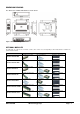
STEP 1: UNPACK
The EBC-3200 is shipped in a plastic bag that is placed inside a
cardboard box. The items are also shipped with the chassis. When
unpacking the chassis please:
Make sure all the items listed in the PACKING LIST
section are present.
Make sure the chassis has not been damaged in any
way.
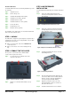
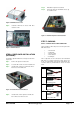
STEP 2: REMOVE THE TOP COVER
The top cover is secured to the chassis with two thumb
screws on the rear panel of the chassis.
Step 1: Loosen the two top cover thumb screws at the
rear panel of the chassis.
Figure 2: Top Cover Retention Screws
Step 2: Slide the cover forwards and then lift the cover up
gently.Step 0:
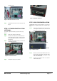
STEP 3: MOTHERBOARD
INSTALLATION
To install a Mini-ITX motherboard, please follow the instructions
below:
Step 1: Remove the USB module bracket from the
chassis by removing the two retention screws on
the front panel.
Figure 3: USB Module Bracket Retention Screws
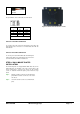
Step 2: Remove the expansion slot bracket shown in the
following diagram from the chassis by removing
the four retention screws.
Figure 4: Expansion Slot Bracket Retention Screws
Step 3: Install the I/O shielding in the chassis. Push the
I/O shielding inside out.
Figure 5: I/O Shielding Installation
Step 4: Place the motherboard inside the right hand side
of the chassis. Make sure the external peripheral
interface connectors fit into the predrilled holes
on the previously installed I/O shielding.
Step 5: Align the four retention screws holes on the
motherboard with the retention screw holes on
the bottom of the chassis.
Step 6: Install the motherboard to the chassis with four