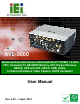
AVL-3000 Advanced Auto Data Server MODEL: AVL-3000 Advanced Auto Data Server with Intel® Atom™ N2600 1.6 GHz CPU, On-board 2.0 GB DDR3 Memory, 802.11b/g/n Wireless, HSUPA, GPS with DR, OBD-II, USB, Audio, 4-Channel Hardware Video Capture, RoHS Compliant User Manual Page i Rev. 2.
AVL-3000 Advanced Auto Data Server Revision Date Version Changes 1 April, 2014 2.02 Changed class B to class A 2 September, 2013 2.01 Added a note for the device ports on page 19 22 April, 2013 2.00 Updated for R20 version Added Chapter 6: Interface Connectors 6 February, 2013 1.01 Updated sections 1.4 Front Panel, 3.7.4 OBD-II Connector (COM4) and 3.7.8 RS-422/485 (COM2) & GPIO Connector 10 September, 2012 Page ii 1.
AVL-3000 Advanced Auto Data Server Copyright COPYRIGHT NOTICE The information in this document is subject to change without prior notice in order to improve reliability, design and function and does not represent a commitment on the part of the manufacturer. In no event will the manufacturer be liable for direct, indirect, special, incidental, or consequential damages arising out of the use or inability to use the product or documentation, even if advised of the possibility of such damages.
AVL-3000 Advanced Auto Data Server Federal Communication Commission Interference Statement This equipment has been tested and found to comply with limits for a class A digital device, pursuant to part 15 of the FCC Rules. These limits are designed to provide reasonable protection against harmful interference in a residential installation.
AVL-3000 Advanced Auto Data Server Table of Contents 1 INTRODUCTION.......................................................................................................... 1 1.1 OVERVIEW.................................................................................................................. 2 1.2 MODEL VARIATIONS ................................................................................................... 2 1.3 FEATURES ......................................................................
AVL-3000 Advanced Auto Data Server 3.8.1 Installation Checklist ....................................................................................... 30 3.8.2 Power-on Procedure ........................................................................................ 30 3.8.3 Power State ...................................................................................................... 31 3.9 SYSTEM MAINTENANCE ...........................................................................................
AVL-3000 Advanced Auto Data Server 5.1.1 SIM CARD Switcher ........................................................................................ 63 5.1.2 Phone ............................................................................................................... 64 6 INTERFACE CONNECTORS ................................................................................... 66 6.1 PERIPHERAL INTERFACE CONNECTORS..................................................................... 67 6.
AVL-3000 Advanced Auto Data Server B.1 ONE KEY RECOVERY INTRODUCTION ...................................................................... 90 B.1.1 System Requirement......................................................................................... 91 B.1.2 Supported Operating System ........................................................................... 92 B.2 SETUP PROCEDURE FOR WINDOWS .......................................................................... 93 B.2.
AVL-3000 Advanced Auto Data Server List of Figures Figure 1-1: AVL-3000 Advanced Auto Data Server .....................................................................2 Figure 1-2: Front Panel ..................................................................................................................4 Figure 1-3: Bottom View ................................................................................................................5 Figure 1-4: Dimensions (unit: mm) ..............................
AVL-3000 Advanced Auto Data Server Figure 5-2: Phone .........................................................................................................................64 Figure 6-1: Main Board Layout Diagram (Front Side) ...............................................................67 Figure 6-2: Main Board Layout Diagram (Solder Side) .............................................................68 Figure B-1: IEI One Key Recovery Tool Menu ...........................................................
AVL-3000 Advanced Auto Data Server Figure B-33: Recovery Tool Menu ........................................................................................... 114 Figure B-34: Recovery Tool Main Menu .................................................................................. 115 Figure B-35: Restore Factory Default ...................................................................................... 116 Figure B-36: Recovery Complete Window ...........................................................
AVL-3000 Advanced Auto Data Server List of Tables Table 1-1: Model Variations ...........................................................................................................2 Table 1-2: Technical Specifications..............................................................................................7 Table 2-1: Packing List.................................................................................................................11 Table 2-2: Optional Items.............................
AVL-3000 Advanced Auto Data Server Table 6-20: Power Input Connector (PWIN1) Pinouts ...............................................................78 Table 6-21: USB Connector (USB1) Pinouts..............................................................................79 Table 6-22: VGA Connector (VGA1) Pinouts .............................................................................
AVL-3000 Advanced Auto Data Server BIOS Menus BIOS Menu 1: Main .......................................................................................................................36 BIOS Menu 2: Advanced ..............................................................................................................37 BIOS Menu 3: RTC Wake Settings ..............................................................................................38 BIOS Menu 4: CPU Configuration ...............................
AVL-3000 Advanced Auto Data Server Chapter 1 1 Introduction Page 1
AVL-3000 Advanced Auto Data Server 1.1 Overview Figure 1-1: AVL-3000 Advanced Auto Data Server The AVL-3000 is an embedded system designed for in-car use. At the heart of the system is the Intel® Atom™ N2600 processor, offering low power in a powerful package. The chipset is rounded off with the Intel® NM10. The AVL-3000 is preinstalled with 2.0 GB DDR3 memory and a 16 GB 2.5” SATA SSD. The system supports HDMI/VGA display output and 802.11b/g/n wireless networking capability.
AVL-3000 Advanced Auto Data Server 1.3 Features All of the AVL-3000 models feature the following: Advanced auto data server with 1.6 GHz Intel® Atom™ N2600 CPU 2.0 GB DDR3 memory preinstalled 16 GB 2.
AVL-3000 Advanced Auto Data Server 1 x Power button 1 x RS-232 COM port (COM1) (DB-9) 4 x RS-232 COM ports (COM7 ~ COM10) (DB-37) 1 x RS-422/485 (COM2) & GPIO connector 1 x SDHC card slot 2 x SIM card slots 1 x VGA connector 1 x Video capture connector 2 x Wi-Fi antenna connectors 4 x UHF RFID antenna connectors 4 x USB ports Figure 1-2: Front Panel Page 4
AVL-3000 Advanced Auto Data Server 1.5 Bottom Panel The bottom panel has VESA mounting screw holes for DIN rail mounting. Figure 1-3: Bottom View 1.6 System Specifications The AVL-3000 technical specifications are listed in Table 1-2. System CPU 1.6 GHz Intel® Atom™ N2600 Chipset Intel® NM10 Memory 2.0 GB 1333 MHz DDR3 preinstalled OS Windows® Embedded Standard 7 preinstalled Storage 1 x 16 GB 2.
AVL-3000 Advanced Auto Data Server Dual-band EV-DO/CDMA GPS GPS with Dead Reckoning support Data Collection RFID Optional IRFR-310 UHF RFID Hardware compression: SC290N4 PCI104 (AVL-3000-N26-HC-R20) Video Capture Video input: 4-channel composite video (NTSC/PAL/SECAM) Frame rate: Total 120fps@QVGA (320x240) for four channels (NTSC), total 100fps@QVGA (320x240) for four channels (PAL/SECAM) Power Power Input 9 V ~ 36 V DC input Cigarette lighter power or ACC power Environmental and Physical Specifica
AVL-3000 Advanced Auto Data Server 4 x RS-232 COM port (COM7 ~ COM10) (DB-37) 1 x RS-422/485 (COM2) & GPIO connector 1 x SDHC card slot 2 x SIM card slots 1 x Video capture connector 1 x VGA connector 4 x USB ports Table 1-2: Technical Specifications Page 7
AVL-3000 Advanced Auto Data Server 1.7 Dimensions The dimensions are shown below.
AVL-3000 Advanced Auto Data Server Chapter 2 2 Unpacking Page 9
AVL-3000 Advanced Auto Data Server To unpack the AVL-3000, follow the steps below: Step 1: Use box cutters, a knife or a sharp pair of scissors that seals the top side of the external (second) box. Step 2: Open the external (second) box. Step 3: Use box cutters, a knife or a sharp pair of scissors that seals the top side of the internal (first) box. Step 4: Lift the monitor out of the boxes. Step 5: Remove both polystyrene ends, one from each side. Step 6: Pull the plastic cover off the AVL-3000.
AVL-3000 Advanced Auto Data Server Quantity Item 1 Capture cable Image (P/N: 32007-001400-100-RS) 1 GPS/GSM antenna (P/N: 32506-000100-100-RS) 2 Wi-Fi antenna (P/N: 32505-000400-100-RS) 1 OBD-II cable (P/N: 32025-000300-100-RS) 1 J1939/FMS cable (P/N: 32025-000400-100-RS) 1 One Key Recovery CD 1 User manual CD and driver CD Table 2-1: Packing List Page 11
AVL-3000 Advanced Auto Data Server The following table lists the optional items that can be purchased separately. Item Image UHF RFID antenna with cable Table 2-2: Optional Items If any of these items are missing or damaged, contact the distributor or sales representative immediately.
AVL-3000 Advanced Auto Data Server Chapter 3 3 Installation Page 13
AVL-3000 Advanced Auto Data Server 3.1 Anti-static Precautions WARNING: Failure to take ESD precautions during the maintenance of the AVL-3000 may result in permanent damage to the AVL-3000 and severe injury to the user. Electrostatic discharge (ESD) can cause serious damage to electronic components, including the AVL-3000. Dry climates are especially susceptible to ESD.
AVL-3000 Advanced Auto Data Server 3.3 Installation and Configuration Steps The following installation steps must be followed. Step 1: Unpack the system Step 2: Install a SIM card or SDHC card (optional) Step 3: Connect peripheral devices Step 4: Mount the system Step 5: Power up the system Step 0: 3.4 SDHC Card Installation To install an SDHC card, follow the instructions below. Step 1: Locate the SDHC card slot. Step 2: Insert the SDHC card into the slot.
AVL-3000 Advanced Auto Data Server 3.5 SIM Card Installation The AVL-3000 has two SIM card slots. To install a SIM card, follow the instructions below. NOTE: The AVL-3000 provides an application for setting which SIM card to use. Refer to Section 5.1.1 for details. Step 1: Locate the SIM card slot. See Figure 3-2. Figure 3-2: SIM Card Slot Locations Step 2: Insert a SIM card into the slot. 3.6 Mounting the System To mount the system onto a DIN rail, please follow the steps below.
AVL-3000 Advanced Auto Data Server Figure 3-3: DIN Rail Mounting Bracket Step 2: Make sure the inserted screw in the center of the bracket is at the lowest position of the elongated hole (Figure 3-4). 75 Figure 3-4: Screw Locations Step 3: Place the DIN rail flush against the back of the mounting bracket making sure the edges of the rail are between the upper and lower clamps (Figure 3-5).
AVL-3000 Advanced Auto Data Server Figure 3-5: Mounting the DIN RAIL Step 4: Secure the DIN rail to the mounting bracket by turning the top screw clockwise. This draws the lower clamp up and secures the AVL-3000 to the DIN rail (Figure 75 3-6).
AVL-3000 Advanced Auto Data Server 3.7 I/O Interface Connectors This section provides an overview of the I/O interface connectors of the AVL-3000. NOTE: The following lists the device ports for the corresponding connectors. RS-422/485: COM 2 OBD-II/CAN: COM 4 GPS: COM 3, COM 5 for data GSM/GPRS: USB port 3.7.1 Audio Connectors The audio jacks connect to external audio devices. Microphone In port (Pink): Connects a microphone. Line Out port (Green): Connects to a headphone or a speaker.
AVL-3000 Advanced Auto Data Server Step 2: Align the connector. Align the HDMI connector with the HDMI port. Make sure the orientation of the connector is correct. Figure 3-8: HDMI Connection Step 3: Insert the HDMI connector. Gently insert the HDMI connector. The connector should engage with a gentle push. If the connector does not insert easily, check again that the connector is aligned correctly, and that the connector is being inserted with the right way up. 3.7.
AVL-3000 Advanced Auto Data Server Figure 3-9: LAN Connection Step 3: Insert the LAN cable RJ-45 connector. Once aligned, gently insert the LAN cable RJ-45 connector into the onboard RJ-45 connector. Step 0: 3.7.4 OBD-II Connector (COM4) The AVL-3000 has one DB-9 male connector for OBD-II connection. Use the OBD-II cable or J1939/FMS cable (Figure 3-10) in the package to connect the AVL-3000 with the vehicle.
AVL-3000 Advanced Auto Data Server Figure 3-11: OBD-II Connector Pinouts Location Pin Description 1 NC 2 NC 3 OBD-CAN_H 4 ISO-9141-2-K 5 OBD-CAN_L 6 J1850- 7 J1850+ 8 ISO-9141-2-L 9 NC Table 3-1: OBD-II Connector Pinouts The pinout locations of OBD-II cable connector and J1939/FMS cable connector are shown below.
AVL-3000 Advanced Auto Data Server Figure 3-13: J1939/FMS Connector Pinouts 3.7.5 Power Input Connection The AVL-3000 has one 12 V DC input connector on the front panel. Figure 3-14: Power Input Connector The AVL-3000 can use either ACC power or DC power from the vehicle. To use DC power, connect the AVL-3000 to the vehicle cigarette lighter connector through the cigarette lighter cable. See Figure 3-15.
AVL-3000 Advanced Auto Data Server Figure 3-16: ACC Power Cable 3.7.6 DB-9 RS-232 COM Port (COM1) The AVL-3000 has one DB-9 RS-232 COM port on the front panel for serial devices to be connected. Follow the steps below to connect a serial device to the AVL-3000. Step 1: Locate the DB-9 connector. The location of the DB-9 connector is shown in Figure 1-2. Step 2: Insert the serial connector. Insert the DB-9 connector of a serial device into the DB-9 connector on the front panel. See Figure 3-17.
AVL-3000 Advanced Auto Data Server Pin Description Pin Description 1 DCD 6 DSR 2 RX 7 RTS 3 TX 8 CTS 4 DTR 9 RI 5 GND Table 3-2: DB-9 RS-232 COM Port (COM1) Pinouts Figure 3-18: DB-9 RS-232 COM Port (COM1) Pinout Location 3.7.7 DB-37 RS-232 COM Port (COM7 ~ COM10) The AVL-3000 has one DB-37 RS-232 COM port on the front panel for serial devices to be connected. The pinouts for the DB-37 connector are listed in the table below.
AVL-3000 Advanced Auto Data Server Figure 3-19: DB-37 RS-232 COM Port (COM7 ~ COM10) Pinout Location 3.7.8 RS-422/485 (COM2) & GPIO Connector The AVL-3000 has one male DB-15 connector on the front panel. The pinouts for the male DB-15 connector are listed in the table below.
AVL-3000 Advanced Auto Data Server Figure 3-20: RS-422/485 & GPIO Connector Pinout Location 3.7.9 USB Device Connection There are four external USB connectors. To connect a USB device, please follow the instructions below. Step 1: Located the USB connectors. The locations of the USB connectors are shown in Figure 1-2. Step 2: Align the connectors. Align the USB device connector with one of the connectors on the front panel. Figure 3-21: USB Device Connection Step 3: Insert the device connector.
AVL-3000 Advanced Auto Data Server 3.7.10 Video Capture Connection The AVL-3000 has one DB-9 female connector for video capture connection. Use the video cable (Figure 3-22) in the package to connect the AVL-3000 with the device. Figure 3-22: Video Capture Cable The pinouts for video connector are listed in the table below.
AVL-3000 Advanced Auto Data Server 3.7.11 VGA Monitor Connection The AVL-3000 has a female DB-15 connector on the front panel. The DB-15 connector is connected to a CRT or VGA monitor. To connect a monitor to the AVL-3000, please follow the instructions below. Step 1: Locate the female DB-15 connector. The location of the female DB-15 connector is shown in Figure 1-2. Step 2: Align the VGA connector.
AVL-3000 Advanced Auto Data Server 3.8 Power-On Procedure 3.8.1 Installation Checklist WARNING: Make sure a power supply with the correct input voltage is being fed into the system. Incorrect voltages applied to the system may cause damage to the internal electronic components and may also cause injury to the user. To power on the AVL-3000, please make sure of the following: The SIM card is installed The bottom cover is installed All peripheral devices (antenna, serial communications devices etc.
AVL-3000 Advanced Auto Data Server Figure 3-25: Power Connector and Power Button 3.8.3 Power State The following table shows the relation of the power state and vehicle ignition system. The auto start-up and shut down time delay can be set by the AVL-3000 software application.
AVL-3000 Advanced Auto Data Server 3.9 System Maintenance If the components of the AVL-3000 fail, they must be replaced. Please contact the system reseller or vendor to purchase the replacement parts. NOTE: A user cannot replace a motherboard. If the motherboard fails it must be shipped back to IEI to be replaced. Please contact the system vendor, reseller or an IEI sales person directly.
AVL-3000 Advanced Auto Data Server Chapter 4 4 BIOS Page 33
AVL-3000 Advanced Auto Data Server 4.1 Introduction The BIOS is programmed onto the BIOS chip. The BIOS setup program allows changes to certain system settings. This chapter outlines the options that can be changed. 4.1.1 Starting Setup The UEFI BIOS is activated when the computer is turned on. The setup program can be activated in one of two ways. 1. Press the DEL or F2 key as soon as the system is turned on or 2.
AVL-3000 Advanced Auto Data Server Key Function Esc key Main Menu – Quit and not save changes into CMOS Status Page Setup Menu and Option Page Setup Menu -Exit current page and return to Main Menu F1 General help, only for Status Page Setup Menu and Option Page Setup Menu F2 Load previous values F3 Load optimized defaults F4 Save changes and Exit BIOS Table 4-1: BIOS Navigation Keys 4.1.
AVL-3000 Advanced Auto Data Server 4.2 Main The Main BIOS menu (BIOS Menu 1) appears when the BIOS Setup program is entered. The Main menu gives an overview of the basic system information. Aptio Setup Utility – Copyright (C) 2011 American Megatrends, Inc. Main Advanced Chipset Boot Security Save & Exit BIOS Information BIOS Vendor Core Version Compliancy Project Version Build Date and Time American Megatrends 4.6.5.1 0.13 UEFI 2.3; PI 1.2 Z181AT21.ROM 12/28/2012 11:53:40 Set the Date.
AVL-3000 Advanced Auto Data Server System Time [xx:xx:xx] Use the System Time option to set the system time. Manually enter the hours, minutes and seconds. 4.3 Advanced Use the Advanced menu (BIOS Menu 2) to configure the CPU and peripheral devices through the following sub-menus: WARNING: Setting the wrong values in the sections below may cause the system to malfunction. Make sure that the settings made are compatible with the hardware. Aptio Setup Utility – Copyright (C) 2011 American Megatrends, Inc.
AVL-3000 Advanced Auto Data Server Aptio Setup Utility – Copyright (C) 2011 American Megatrends, Inc. Advanced Wake system with Fixed Time [Disabled] Enable or disable System wake on alarm event. When enabled, System will wake on the date::hr::min::sec specified ---------------------- : Select Screen ↑ ↓: Select Item Enter: Select +/-: Change Opt. F1: General Help F2: Previous Values F3: Optimized Defaults F4: Save & Exit ESC: Exit Version 2.14.1219. Copyright (C) 2011 American Megatrends, Inc.
AVL-3000 Advanced Auto Data Server 4.3.2 CPU Configuration Use the CPU Configuration menu (BIOS Menu 4) to view detailed CPU specifications and configure the CPU. Aptio Setup Utility – Copyright (C) 2011 American Megatrends, Inc. Advanced CPU Configuration Processor Type EMT64 Processor Speed System Bus Speed Ratio Status Actual Ratio System Bus Speed Processor Stepping Microcode Revision L1 Cache RAM L2 Cache RAM Processor Core Hyper-Threading Intel(R) Atom(TM) CPU N2600 @ 1.
AVL-3000 Advanced Auto Data Server Hyper-Threading [Enabled] Use the Hyper-Threading BIOS option to enable or disable the Intel Hyper-Threading Technology. Disables the Intel Hyper-Threading Technology. Disabled Enabled DEFAULT Enables the Intel Hyper-Threading Technology. 4.3.3 IDE Configuration Use the IDE Configuration menu (BIOS Menu 5) to change and/or set the configuration of the SATA devices installed in the system. Aptio Setup Utility – Copyright (C) 2011 American Megatrends, Inc.
AVL-3000 Advanced Auto Data Server 4.3.4 USB Configuration Use the USB Configuration menu (BIOS Menu 6) to read USB configuration information and configure the USB settings. Aptio Setup Utility – Copyright (C) 2011 American Megatrends, Inc. Advanced USB Configuration USB Devices: None Legacy USB Support [Enabled] Enables Legacy USB support. AUTO option disables legacy support if no USB devices are connected. DISABLE option will keep USB devices available only for EFI applications.
AVL-3000 Advanced Auto Data Server 4.3.5 F81866 Super IO Configuration Use the F818666 Super IO Configuration menu (BIOS Menu 7) to set or change the configurations for the serial ports. Aptio Setup Utility – Copyright (C) 2011 American Megatrends, Inc.
AVL-3000 Advanced Auto Data Server 4.3.5.1.1 Serial Port 1 Configuration Serial Port [Enabled] Use the Serial Port option to enable or disable the serial port. Disable the serial port Disabled Enabled DEFAULT Enable the serial port Change Settings [Auto] Use the Change Settings option to change the serial port IO port address and interrupt address. Auto DEFAULT The serial port IO port address and interrupt address are automatically detected.
AVL-3000 Advanced Auto Data Server Change Settings [Auto] Use the Change Settings option to change the serial port IO port address and interrupt address. Auto DEFAULT The serial port IO port address and interrupt address are automatically detected.
AVL-3000 Advanced Auto Data Server IO=2F8h; Serial Port I/O port address is 2F8h and the interrupt IRQ=10 address is IRQ10 IO=250h; Serial Port I/O port address is 250h and the interrupt IRQ=10 address is IRQ10 4.3.6 F81866 H/W Monitor The F81866 H/W Monitor menu (BIOS Menu 9) displays the CPU and system temperatures. Aptio Setup Utility – Copyright (C) 2011 American Megatrends, Inc.
AVL-3000 Advanced Auto Data Server 4.3.7 F81216 Second Super IO Configuration Use the F81216 Second Super IO Configuration menu (BIOS Menu 10) to set or change the configurations for the serial ports. Aptio Setup Utility – Copyright (C) 2011 American Megatrends, Inc. Advanced F81216 Second Super IO Configuration F81216 Second > Serial Port > Serial Port > Serial Port > Serial Port Super IO Chip 7 Configuration 8 Configuration 9 Configuration 10 Configuration Set Parameters of Serial Port 7 (SEC.
AVL-3000 Advanced Auto Data Server 4.3.7.1.1 Serial Port 7 Configuration Serial Port [Enabled] Use the Serial Port option to enable or disable the serial port. Disable the serial port Disabled Enabled DEFAULT Enable the serial port Change Settings [Auto] Use the Change Settings option to change the serial port IO port address and interrupt address. Auto DEFAULT The serial port IO port address and interrupt address are automatically detected.
AVL-3000 Advanced Auto Data Server Change Settings [Auto] Use the Change Settings option to change the serial port IO port address and interrupt address. Auto DEFAULT The serial port IO port address and interrupt address are automatically detected.
AVL-3000 Advanced Auto Data Server IO=260h; Serial Port I/O port address is 260h and the IRQ=10, 11, 12 interrupt address is IRQ10, 11, 12 IO=268h; Serial Port I/O port address is 268h and the IRQ=10, 11, 12 interrupt address is IRQ10, 11, 12 IO=270h; Serial Port I/O port address is 270h and the IRQ=10, 11, 12 interrupt address is IRQ10, 11, 12 IO=278h; Serial Port I/O port address is 278h and the IRQ=10, 11, 12 interrupt address is IRQ10, 11, 12 4.3.7.1.
AVL-3000 Advanced Auto Data Server 4.3.8 Serial Port Console Redirection The Serial Port Console Redirection menu (BIOS Menu 12) allows the console redirection options to be configured. Console redirection allows users to maintain a system remotely by re-directing keyboard input and text output through the serial port. Aptio Setup Utility – Copyright (C) 2011 American Megatrends, Inc.
AVL-3000 Advanced Auto Data Server Terminal Type [ANSI] Use the Terminal Type option to specify the remote terminal type. VT100 The target terminal type is VT100 VT100+ The target terminal type is VT100+ VT-UTF8 The target terminal type is VT-UTF8 ANSI DEFAULT The target terminal type is ANSI Bits per second [115200] Use the Bits per second option to specify the serial port transmission speed. The speed must match the other side. Long or noisy lines may require lower speeds.
AVL-3000 Advanced Auto Data Server The parity bit is always 1. This option does not Mark provide error detection. The parity bit is always 0. This option does not Space provide error detection. Stop Bits [1] Use the Stop Bits option to specify the number of stop bits used to indicate the end of a serial data packet. Communication with slow devices may require more than 1 stop bit. 1 DEFAULT 2 Sets the number of stop bits at 1. Sets the number of stop bits at 2. 4.3.
AVL-3000 Advanced Auto Data Server Auto Recovery Function [Disabled] Use the Auto Recovery Function BIOS option to enable or disable the auto recovery function of the IEI One Key Recovery. Disabled Auto recovery function disabled DEFAULT Auto recovery function enabled Enabled 4.3.10 Power Management Use the Power Management menu (BIOS Menu 14) to configure the power management function. Aptio Setup Utility – Copyright (C) 2011 American Megatrends, Inc.
AVL-3000 Advanced Auto Data Server 30 sec 1 min 5 min 10 min 15 min 30 min 1 hour Auto Power Off Delay [20 sec] Use the Auto Power Off Delay option to set the automatic power-off delay time. Configuration options are listed below. 20 sec DEFAULT 1 min 5 min 10 min 30 min 1 hour 6 hour 18 hour 4.4 Chipset Use the Chipset menu (BIOS Menu 15) to access the Host Bridge and Southbridge configuration menus.
AVL-3000 Advanced Auto Data Server Aptio Setup Utility – Copyright (C) 2011 American Megatrends, Inc. Main Advanced Chipset Boot Security Save & Exit > Host Bridge > South Bridge Host Bridge Parameters --------------------: Select Screen ↑ ↓: Select Item Enter: Select +/-: Change Opt. F1: General Help F2: Previous Values F3: Optimized Defaults F4: Save & Exit ESC: Exit Version 2.14.1219. Copyright (C) 2011 American Megatrends, Inc. BIOS Menu 15: Chipset 4.4.
AVL-3000 Advanced Auto Data Server 4.4.1.1 Intel IGD Configuration Use the Intel IGD Configuration submenu (BIOS Menu 17) to configure the video device connected to the system. Aptio Setup Utility – Copyright (C) 2011 American Megatrends, Inc. Advanced Intel IGD Configuration IGFX – Boot Type Fixed Graphics Memory Size [VBIOS Default] [256MB] Select the Video Device which will be activated during POST. This has no effect if external graphics present.
AVL-3000 Advanced Auto Data Server 4.4.2 South Bridge Configuration Use the South Bridge Configuration menu (BIOS Menu 18) to configure the Southbridge chipset. Aptio Setup Utility – Copyright (C) 2011 American Megatrends, Inc. Chipset Set Spread Spectrum function [Disabled] Set Spread Spectrum Disable/Enable. --------------------- : Select Screen ↑ ↓: Select Item Enter: Select +/-: Change Opt. F1: General Help F2: Previous Values F3: Optimized Defaults F4: Save & Exit ESC: Exit Version 2.14.1219.
AVL-3000 Advanced Auto Data Server 4.5 Boot Use the Boot menu (BIOS Menu 19) to configure system boot options. Aptio Setup Utility – Copyright (C) 2011 American Megatrends, Inc.
AVL-3000 Advanced Auto Data Server Quiet Boot [Enabled] Use the Quiet Boot BIOS option to select the screen display when the system boots. Normal POST messages displayed Disabled Enabled DEFAULT OEM Logo displayed instead of POST messages Launch PXE OpROM [Disabled] Use the Launch PXE OpROM option to enable or disable boot option for legacy network devices. Disabled DEFAULT Ignore all PXE Option ROMs Load PXE Option ROMs.
AVL-3000 Advanced Auto Data Server 4.6 Security Use the Security menu (BIOS Menu 20) to set system and user passwords. Aptio Setup Utility – Copyright (C) 2011 American Megatrends, Inc. Main Advanced Chipset Boot Security Save & Exit Password Description If ONLY the Administrator’s password is set, then this only limits access to Setup and is only asked for when entering Setup. If ONLY the User’s password is set, then this is a power on password and must be entered to boot or enter Setup.
AVL-3000 Advanced Auto Data Server Aptio Setup Utility – Copyright (C) 2011 American Megatrends, Inc. Main Advanced Chipset Boot Security Save & Exit Save Changes and Reset Discard Changes and Reset Reset the system after saving the changes. Restore Defaults Save as User Defaults Restore User Defaults --------------------- : Select Screen ↑ ↓: Select Item Enter: Select +/-: Change Opt. F1: General Help F2: Previous Values F3: Optimized Defaults F4: Save & Exit ESC: Exit Version 2.14.1219.
AVL-3000 Advanced Auto Data Server Chapter 5 5 Application Tools Page 62
AVL-3000 Advanced Auto Data Server 5.1 Introduction The following sections introduce two application tools in the AVL-3000. 5.1.1 SIM CARD Switcher The SIM CARD Switcher allows users to switch which SIM card to use. To launch the application, double click the SimSwitcher icon on the Windows desktop. Figure 5-1: SIM CARD Switcher Set SIM: Allows users to designate which SIM card to use or select SIM AUTO to let the system detect automatically.
AVL-3000 Advanced Auto Data Server 5.1.2 Phone The Phone application allows users to make a phone call, select to use a Bluetooth headset or wired headset, and adjust the headset volume. To launch the application, double click the DialDialog icon on the Windows desktop. NOTE: The Phone application can be used only when a 3G card with voice function is installed. Figure 5-2: Phone Back: Click to delete a previously entered number. Call: Click to place a phone call after entering the phone number.
AVL-3000 Advanced Auto Data Server End Call: Click to end a phone call. Bluetooth/HeadSet: Toggles between a Bluetooth headset and wired headset. / (Volume up/Volume down): Adjusts the headset volume. .
AVL-3000 Advanced Auto Data Server Chapter 6 6 Interface Connectors Page 66
AVL-3000 Advanced Auto Data Server 6.1 Peripheral Interface Connectors The AVL-3000 motherboard comes with a number of peripheral interface connectors. The connector locations are shown in Figure 6-1 and Figure 6-2. The Pin 1 locations of the on-board connectors are also indicated in the diagrams. The connector pinouts for these connectors are listed in the following sections.
AVL-3000 Advanced Auto Data Server Figure 6-2: Main Board Layout Diagram (Solder Side) 6.2 Internal Peripheral Connectors Internal peripheral connectors are found on the motherboard and are only accessible when the motherboard is outside of the chassis. The table below shows a list of the peripheral interface connectors on the AVL-3000 motherboard. Pinouts of these connectors can be found in the following sections.
AVL-3000 Advanced Auto Data Server Connector Type Label PCIe Mini card slots 52-pin PCIe Mini slot MINI_PCIE1, MINI_PCIE2, MINI_PCIE3 Power button and LED connector 4-pin wafer PW_BTN1 Programmer connectors 5-pin header JOBD1, MCU1 RS-232 serial port connectors 10-pin header, COM1, COM6, 40-pin header JCOM7 Serial ATA (SATA) drive connector 7-pin SATA SATA1 SPI flash connector 6-pin wafer SPI1 USB 2.0 connector 4-pin wafer USB5 Table 6-1: Peripheral Interface Connectors 6.2.
AVL-3000 Advanced Auto Data Server 6.2.3 Digital I/O and RS-422/485 Connector (DIO/RS422/485_1) PIN NO. DESCRIPTION PIN NO. DESCRIPTION 1 DIN0 2 DOUT0 3 DIN1 4 DOUT1 5 DIN2 6 DOUT2 7 DIN3 8 DOUT3 9 VCC5 10 GND 11 TXD485# 12 TXD485+ 13 RXD485# 14 RXD485+ Table 6-4: Digital I/O and RS-422/485 Connector (DIO/RS422/485_1) Pinouts 6.2.4 LPC Debug Card Connector (DBG_PORT1) PIN NO.
AVL-3000 Advanced Auto Data Server 6.2.5 OBD-II Connector (OBDII1) PIN NO. DESCRIPTION PIN NO. DESCRIPTION 1 NC 2 J1850- 3 NC 4 J1850+ 5 OBD-CAN_H 6 ISO-9141-2-L 7 ISO-9141-2-K 8 NC 9 OBD-CAN_L 10 NC Table 6-6: OBD-II Connector (OBDII1) Pinouts 6.2.
AVL-3000 Advanced Auto Data Server 6.2.7 PCIe Mini Card Slot, Supporting Wi-Fi Card (MINI_PCIE1) PIN NO. DESCRIPTION PIN NO. DESCRIPTION 1 WAKE# 2 VCC3 3 NC 4 GND 5 NC 6 VCC1.5 7 NC 8 NC 9 GND 10 NC 11 CLK_PCIE_CLK_N 12 NC 13 CLK_PCIE_CLK_P 14 NC 15 GND 16 NC 17 NC 18 GND 19 NC 20 DISABLE 21 GND 22 PCIRST# 23 PCIE_RXN 24 VCC3 25 PCIE_RXP 26 GND 27 GND 28 VCC1.
AVL-3000 Advanced Auto Data Server 6.2.8 PCIe Mini Card Slot, Supporting 3G Card (MINI_PCIE2) PIN NO. DESCRIPTION PIN NO. DESCRIPTION 1 MIC_P 2 VCC3 3 MIC_N 4 GND 5 SPK_P 6 VCC1.5 7 SPK_N 8 SIM_VCC 9 GND 10 SIM_CIO 11 NC 12 SIM_CLK 13 NC 14 SIM_RST 15 GND 16 NC 17 NC 18 GND 19 NC 20 DISABLE 21 GND 22 PCIRST# 23 NC 24 VCC3 25 NC 26 GND 27 GND 28 VCC1.
AVL-3000 Advanced Auto Data Server 6.2.9 PCIe Mini Card Slot, Supporting Capture Card (MINI_PCIE3) PIN NO. DESCRIPTION PIN NO. DESCRIPTION 1 WAKE# 2 VCC3 3 NC 4 GND 5 NC 6 VCC1.5 7 NC 8 NC 9 GND 10 NC 11 CLK_PCIE_CLK_N 12 NC 13 CLK_PCIE_CLK_P 14 NC 15 GND 16 NC 17 NC 18 GND 19 NC 20 DISABLE 21 GND 22 PCIRST# 23 PCIE_RXN 24 VCC3 25 PCIE_RXP 26 GND 27 GND 28 VCC1.
AVL-3000 Advanced Auto Data Server 6.2.10 Power Button and LED Connector (PWR_BTN1) PIN NO. DESCRIPTION 1 PWRBTIN 2 GND 3 PWR_LED 4 GND Table 6-11: Power Button and LED Connector (PWR_BTN1) Pinouts 6.2.11 Programmer Connectors (JOBD1, MCU1) PIN NO. DESCRIPTION 1 MCLR 2 VCC5 3 GND 4 ICSP_CLK 5 ICSP_DAT Table 6-12: Programmer Connectors (JOBD1, MCU1) Pinouts 6.2.12 RS-232 Serial Port Connector, Four Ports (JCOM7) PIN NO. DESCRIPTION PIN NO.
AVL-3000 Advanced Auto Data Server PIN NO. DESCRIPTION PIN NO. DESCRIPTION 21 DCD9 22 DSR9 23 RX9 24 RTS9 25 TX9 26 CTS9 27 DTR9 28 RI9 29 GND 30 GND 31 DCD10 32 DSR10 33 RX10 34 RTS10 35 TX10 36 CTS10 37 DTR10 38 RI10 39 GND 40 GND Table 6-13: RS-232 Serial Port Connector, Four Ports (JCOM7) Pinouts 6.2.13 RS-232 Serial Port Connectors (COM1, COM6) PIN NO. DESCRIPTION PIN NO.
AVL-3000 Advanced Auto Data Server 6.2.14 SATA Drive Connector (SATA1) PIN NO. DESCRIPTION 1 GND 2 SATA_TXP 3 SATA_TXN 4 GND 5 SATA_RXN 6 SATA_RXP 7 GND Table 6-15: SATA Drive Connector (SATA1) Pinouts 6.2.15 SPI Flash Connector (SPI1) PIN NO. DESCRIPTION 1 VCC3 2 CS 3 MISO 4 CLK 5 MOSI 6 GND Table 6-16: SPI Flash Connector (SPI1) Pinouts 6.2.16 USB 2.0 Connector (USB5) PIN NO. DESCRIPTION 1 VCC5 2 DATA- 3 DATA+ 4 GND Table 6-17: USB 2.
AVL-3000 Advanced Auto Data Server 6.3 External Interface Panel Connectors The table below lists the rear panel connectors on the AVL-3000 motherboard. Pinouts of these connectors can be found in the following sections. Connector Type Label Audio connector Audio jack AUDIO1 Dual USB 2.0 port Dual USB 2.0 port USB3 Ethernet and USB 2.0 connectors RJ-45, USB 2.
AVL-3000 Advanced Auto Data Server 6.3.3 USB 2.0 Connectors (USB3, LAN1_USB1) PIN NO. DESCRIPTION PIN NO. DESCRIPTION 1 VCC 2 VCC 2 DATA- 4 DATA- 3 DATA+ 6 DATA+ 4 GROUND 8 GROUND Table 6-21: USB Connector (USB1) Pinouts 6.3.4 VGA Connector (VGA1) PIN NO. DESCRIPTION PIN NO.
AVL-3000 Advanced Auto Data Server Appendix A A OBD-II Reader Command Page 80
AVL-3000 Advanced Auto Data Server A.1 Select a Chip Initial Mode: UpDate F/W or RUN F/W AP sends query F/W receives query 1 Enter Boot 0x3 Mode 1 Enter RUN 0x3 Mode 0 2 3 4 5 6 7 8 9 10 11 12 13 14 15 16 17 18 19 A.2 Boot Mode Launch AP: P1618QP (Pic18F Bootloader ) Baud Rate:115200 A.
AVL-3000 Advanced Auto Data Server F/W returns (after receiving query) Select a 1 2 3 4 5 6 7 8 $ M 0 0x0 Ver Ver 0x0 0x0 0 (1) (2) A D 0x1 0x0 0 6 0x0 Ver Ver 0x0 0x0 0 (1) (2) A D 0x1 0x0 0 6 0x0 Ver Ver 0x0 0x0 0 (1) (2) A D 0x1 0x0 0 6 mode to send Tele mode $ M 1 response CAN S $ M 2 mode response Enter Tele $ M T mode to 0x0 0x0 A D 0x0 0x0 A D respond Enter CAN $ S mode to respond Page 82 M C 9 10 11 12 13 14 1
AVL-3000 Advanced Auto Data Server A.4 Into CAN_Standard V2.2.
AVL-3000 Advanced Auto Data Server complete Menu setup $ C 4 0x0A D complete Read query 0x0 $ C 5 setup xxx TxID Bau E d RTR ID(1) ID(2) ID(3) ID(4) D1 D2 D3 D4 D5 D6 D7 D8 0x0A 0x0 D B0 B1 DLC Read menu $ C 7 setup M1I M1I M1I M1I M1F M1F M1F M1F M1F M1F M1F M1F M2I M2I M2I M2I D(1) D(2) D(3) D(4) 1ID( 1ID( 1ID( 1ID( 2ID( 2ID( 2ID( 2ID( D(1) D(2) D(3) D(4) 1) 2) 3) 4) 1) 2) 3) 4) 0x0A 0x0 M2F M2F M2F M2F M2F M2F M2F M2F M
AVL-3000 Advanced Auto Data Server A.5 Into Telematics (Vehicel Information) F/W:Telematics AP: Telematics V1.
AVL-3000 Advanced Auto Data Server Reserved H J1939 input I PSPF FMS input J PSPF Version Y P P P P 0x0 -1 -2 -1 -2 D P P P P 0x0 -1 -2 -1 -2 D 0x0 D F/W returns (after receiving query) 1 No device is scanned Devices Scanned Page 86 2 3 4 5 6 7 8 9 10 11 12 13 14 15 16 17 18 19
AVL-3000 Advanced Auto Data Server OBD packet format (ASCII code) OBD packet has five different format, they are: 1. CAN 11bits 250 2. CAN 29bits 250 3. CAN 11bits 500 4. CAN 29bits 500 5.
AVL-3000 Advanced Auto Data Server Byte 4 define as A. (same with the PID code table on Wikipedia) Byte 5 define as B. (same with the PID code table on Wikipedia) Byte 6 define as C. (same with the PID code table on Wikipedia) Byte 7 define as D.
AVL-3000 Advanced Auto Data Server Appendix B B One Key Recovery Page 89
AVL-3000 Advanced Auto Data Server B.1 One Key Recovery Introduction The IEI one key recovery is an easy-to-use front end for the Norton Ghost system backup and recovery tool. This tool provides quick and easy shortcuts for creating a backup and reverting to that backup or reverting to the factory default settings.
AVL-3000 Advanced Auto Data Server After completing the five initial setup procedures as described above, users can access the recovery tool by pressing while booting up the system. The detailed information of each function is described in Section B.5. NOTE: The initial setup procedures for Linux system are described in Section B.3. 75 B.1.1 System Requirement NOTE: The recovery CD can only be used with IEI products.
AVL-3000 Advanced Auto Data Server partitions. Please take the following table as a reference when calculating the size of the partition. OS OS Image after Ghost Compression Ratio Windows® 7 7 GB 5 GB 70% Windows® XPE 776 MB 560 MB 70% Windows® CE 6.0 36 MB 28 MB 77% NOTE: Specialized tools are required to change the partition size if the operating system is already installed. B.1.
AVL-3000 Advanced Auto Data Server Linux o o o o o o o o o o o o o o Fedora Core 12 (Constantine) Fedora Core 11 (Leonidas) Fedora Core 10 (Cambridge) Fedora Core 8 (Werewolf) Fedora Core 7 (Moonshine) RedHat RHEL-5.4 RedHat 9 (Ghirke) Ubuntu 8.10 (Intrepid) Ubuntu 7.10 (Gutsy) Ubuntu 6.10 (Edgy) Debian 5.0 (Lenny) Debian 4.0 (Etch) SuSe 11.2 SuSe 10.3 NOTE: Installing unsupported OS versions may cause the recovery tool to fail. B.
AVL-3000 Advanced Auto Data Server The detailed descriptions are described in the following sections. NOTE: The setup procedures described below are for Microsoft Windows operating system users. For Linux, most of the setup procedures are the same except for several steps described in Section B.3. 75 B.2.1 Hardware and BIOS Setup Step 1: Make sure the system is powered off and unplugged. Step 2: Install a hard drive or SSD in the system. An unformatted and unpartitioned disk is recommended.
AVL-3000 Advanced Auto Data Server Step 2: Boot the system from recovery CD. When prompted, press any key to boot from the recovery CD. It will take a while to launch the recovery tool. Please be patient! Figure B-2: Launching the Recovery Tool Step 3: The recovery tool setup menu is shown as below. Figure B-3: Recovery Tool Setup Menu Step 4: Press <6> then .
AVL-3000 Advanced Auto Data Server Figure B-4: Command Prompt Step 5: The command prompt window appears. Type the following commands (marked in red) to create two partitions. One is for the OS installation; the other is for saving recovery files and images which will be an invisible partition.
AVL-3000 Advanced Auto Data Server Figure B-5: Partition Creation Commands Page 97
AVL-3000 Advanced Auto Data Server NOTE: Use the following commands to check if the partitions were created successfully. Step 6: Press any key to exit the recovery tool and automatically reboot the system. Please continue to the following procedure: Build the Recovery Partition.Step0: B.2.3 Install Operating System, Drivers and Applications Install the operating system onto the unlabelled partition.
AVL-3000 Advanced Auto Data Server B.2.4 Build-up Recovery Partition Step 1: Put the recover CD in the optical drive. Step 2: Start the system. Step 3: Boot the system from the recovery CD. When prompted, press any key to boot from the recovery CD. It will take a while to launch the recovery tool. Please be patient! Figure B-6: Launching the Recovery Tool Step 4: When the recovery tool setup menu appears, press <2> then .
AVL-3000 Advanced Auto Data Server Step 5: The Symantec Ghost window appears and starts configuring the system to build a recovery partition. In this process the partition created for recovery files in Section B.2.2 is hidden and the recovery tool is saved in this partition. 75 Figure B-8: Building the Recovery Partition Step 6: After completing the system configuration, press any key in the following window to reboot the system. Figure B-9: Press Any Key to Continue Step 7: Eject the recovery CD.
AVL-3000 Advanced Auto Data Server B.2.5 Create Factory Default Image NOTE: Before creating the factory default image, please configure the system to a factory default environment, including driver and application installations. To create a factory default image, please follow the steps below. Step 1: Turn on the system. When the following screen displays (Figure B-10), press 75 the key to access the recovery tool.
AVL-3000 Advanced Auto Data Server Figure B-12: About Symantec Ghost Window Step 4: Use mouse to navigate to the option shown below (Figure B-13). 75 Figure B-13: Symantec Ghost Path Step 5: Select the local source drive (Drive 1) as shown in Figure B-14. Then click OK.
AVL-3000 Advanced Auto Data Server Figure B-14: Select a Local Source Drive Step 6: Select a source partition (Part 1) from basic drive as shown in Figure B-15. 75 Then click OK. Figure B-15: Select a Source Partition from Basic Drive Step 7: Select 1.2: [Recovery] NTFS drive and enter a file name called iei (Figure B-16). Click Save. The factory default image will then be saved in the 75 selected recovery drive and named IEI.GHO. WARNING: The file name of the factory default image must be iei.GHO.
AVL-3000 Advanced Auto Data Server Figure B-16: File Name to Copy Image to Step 8: When the Compress Image screen in Figure B-17 prompts, click High to make 75 the image file smaller.
AVL-3000 Advanced Auto Data Server Step 9: The Proceed with partition image creation window appears, click Yes to continue. Figure B-18: Image Creation Confirmation Step 10: The Symantec Ghost starts to create the factory default image (Figure B-19). 75 Figure B-19: Image Creation Complete Step 11: When the image creation completes, a screen prompts as shown in Figure B-20. 75 Click Continue and close the Ghost window to exit the program.
AVL-3000 Advanced Auto Data Server Step 12: The recovery tool main menu window is shown as below. Press any key to reboot the system. Step0: Figure B-21: Press Any Key to Continue B.3 Auto Recovery Setup Procedure The auto recovery function allows a system to automatically restore from the factory default image after encountering a Blue Screen of Death (BSoD) or a hang for around 10 minutes. To use the auto recovery function, follow the steps described in the following sections.
AVL-3000 Advanced Auto Data Server Step 1: Follow the steps described in Section B.2.1 ~ Section B.2.3 to setup BIOS, create partitions and install operating system. Step 2: Install the auto recovery utility into the system by double clicking the Utility/AUTORECOVERY-SETUP.exe in the One Key Recovery CD. This utility MUST be installed in the system, otherwise, the system will automatically restore from the factory default image every ten (10) minutes.
AVL-3000 Advanced Auto Data Server Step 4: Reboot the system from the recovery CD. When prompted, press any key to boot from the recovery CD. It will take a while to launch the recovery tool. Please be patient! Figure B-24: Launching the Recovery Tool Step 5: When the recovery tool setup menu appears, press <4> then . Figure B-25: Auto Recovery Environment for Windows Step 6: The Symantec Ghost window appears and starts configuring the system to build an auto recovery partition.
AVL-3000 Advanced Auto Data Server Figure B-26: Building the Auto Recovery Partition Step 7: After completing the system configuration, the following message prompts to confirm whether to create a factory default image. Type Y to have the system create a factory default image automatically. Type N within 6 seconds to skip this process (The default option is YES). It is suggested to choose YES for this option.
AVL-3000 Advanced Auto Data Server Step 8: The Symantec Ghost starts to create the factory default image (Figure B-28). Figure B-28: Image Creation Complete Step 9: After completing the system configuration, press any key in the following window to restart the system. Figure B-29: Press any key to continue Step 10: Eject the One Key Recovery CD and restart the system. Step 11: Press the key as soon as the system is turned on to enter the BIOS.
AVL-3000 Advanced Auto Data Server Main Advanced PCIPNP BIOS SETUP UTILITY Boot Security Chipset Exit iEi Feature ⎯⎯⎯⎯⎯⎯⎯⎯⎯⎯⎯⎯⎯⎯⎯⎯⎯⎯⎯⎯⎯⎯⎯⎯⎯⎯⎯ Auto Recovery Function [Enabled] Recover from PXE [Disabled] ↑ ↓ Enter F1 F10 ESC Select Screen Select Item Go to SubScreen General Help Save and Exit Exit v02.61 ©Copyright 1985-2006, American Megatrends, Inc. BIOS Menu 22: IEI Feature Step 13: Save changes and restart the system.
AVL-3000 Advanced Auto Data Server Partition 1: / Partition 2: SWAP NOTE: Please reserve enough space for partition 3 for saving recovery images. Figure B-30: Partitions for Linux Step 3: Create a recovery partition. Insert the recovery CD into the optical disk drive. Follow Step 1 ~ Step 3 described in Section B.2.2. Then type the following 75 commands (marked in red) to create a partition for recovery images.
AVL-3000 Advanced Auto Data Server recovery partition. After completing the system configuration, press any key to reboot the system. Eject the recovery CD. Figure B-31: System Configuration for Linux Step 5: Access the recovery tool main menu by modifying the “menu.lst”. To first access the recovery tool main menu, the menu.lst must be modified. In Linux, enter Administrator (root). When prompt appears, type: cd /boot/grub vi menu.lst Figure B-32: Access menu.
AVL-3000 Advanced Auto Data Server Step 7: The recovery tool menu appears. (Figure B-33) 75 Figure B-33: Recovery Tool Menu Step 8: Create a factory default image. Follow Step 2 ~ Step 12 described in Section B.2.5 to create a factory default image. 75 B.5 Recovery Tool Functions After completing the initial setup procedures as described above, users can access the recovery tool by pressing while booting up the system. However, if the setup procedure in Section B.
AVL-3000 Advanced Auto Data Server Figure B-34: Recovery Tool Main Menu The recovery tool has several functions including: 1. Factory Restore: Restore the factory default image (iei.GHO) created in Section B.2.5. 75 2. Backup system: Create a system backup image (iei_user.GHO) which will be saved in the hidden partition. 3. Restore your last backup: Restore the last system backup image 4. Manual: Enter the Symantec Ghost window to configure manually. 5. Quit: Exit the recovery tool and restart the system.
AVL-3000 Advanced Auto Data Server B.5.1 Factory Restore To restore the factory default image, please follow the steps below. Step 1: Type <1> and press in the main menu. Step 2: The Symantec Ghost window appears and starts to restore the factory default. A factory default image called iei.GHO is created in the hidden Recovery partition. Figure B-35: Restore Factory Default Step 3: The screen is shown in Figure B-36 appears when completed. Press any key to 75 reboot the system.
AVL-3000 Advanced Auto Data Server B.5.2 Backup System To backup the system, please follow the steps below. Step 1: Type <2> and press in the main menu. Step 2: The Symantec Ghost window appears and starts to backup the system. A backup image called iei_user.GHO is created in the hidden Recovery partition. Figure B-37: Backup System Step 3: The screen is shown in Figure B-38 appears when system backup is complete. 75 Press any key to reboot the system.
AVL-3000 Advanced Auto Data Server B.5.3 Restore Your Last Backup To restore the last system backup, please follow the steps below. Step 1: Type <3> and press in the main menu. Step 2: The Symantec Ghost window appears and starts to restore the last backup image (iei_user.GHO). Figure B-39: Restore Backup Step 3: The screen shown in Figure B-40 appears when backup recovery is complete. 76 Press any key to reboot the system.
AVL-3000 Advanced Auto Data Server B.5.4 Manual To restore the last system backup, please follow the steps below. Step 1: Type <4> and press in the main menu. Step 2: The Symantec Ghost window appears. Use the Ghost program to backup or recover the system manually. Figure B-41: Symantec Ghost Window Step 3: When backup or recovery is completed, press any key to reboot the system.
AVL-3000 Advanced Auto Data Server B.6 Restore Systems from a Linux Server through LAN The One Key Recovery allows a client system to automatically restore to a factory default image saved in a Linux system (the server) through LAN connectivity after encountering a Blue Screen of Death (BSoD) or a hang for around 10 minutes. To be able to use this function, the client system and the Linux system MUST reside in the same domain.
AVL-3000 Advanced Auto Data Server B.6.1 Configure DHCP Server Settings Step 1: Install the DHCP #yum install dhcp (CentOS, commands marked in red) #apt-get install dhcp3-server (Debian, commands marked in blue) Step 2: Confirm the operating system default settings: dhcpd.conf. CentOS Use the following command to show the DHCP server sample location: #vi /etc/dhcpd.conf The DHCP server sample location is shown as below: Use the following command to copy the DHCP server sample to etc/dhcpd.
AVL-3000 Advanced Auto Data Server filename “pxelinux.0”; B.6.2 Configure TFTP Settings Step 1: Install the tftp, httpd and syslinux. #yum install tftp-server httpd syslinux (CentOS) #apt-get install tftpd-hpa xinetd syslinux (Debian) Step 2: Enable the TFTP server by editing the “/etc/xinetd.d/tftp” file and make it use the remap file. The “-vvv” is optional but it could definitely help on getting more information while running the remap file. For example: CentOS #vi /etc/xinetd.
AVL-3000 Advanced Auto Data Server Debian Replace the TFTP settings from “inetd” to “xinetd” and annotate the “inetd” by adding “#”. #vi /etc/inetd.conf Modify: #tftp dgram udp wait root /usr/sbin....... (as shown below) #vi /etc/xinetd.d/tftp B.6.3 Configure One Key Recovery Server Settings Step 1: Copy the Utility/RECOVERYR10.TAR.BZ2 package from the One Key Recovery CD to the system (server side). Step 2: Extract the recovery package to /. #cp RecoveryR10.tar.bz2 / #cd / #tar –xvjf RecoveryR10.tar.
AVL-3000 Advanced Auto Data Server B.6.4 Start the DHCP, TFTP and HTTP Start the DHCP, TFTP and HTTP. For example: CentOS #service xinetd restart #service httpd restart #service dhcpd restart Debian #/etc/init.d/xinetd reload #/etc/init.d/xinetd restart #/etc/init.d/dhcp3-server restart B.6.5 Create Shared Directory Step 1: Install the samba. #yum install samba Step 2: Create a shared directory for the factory default image. #mkdir /share #cd /share #mkdir /image #cp iei.
AVL-3000 Advanced Auto Data Server Modify: [image] comment = One Key Recovery path = /share/image browseable = yes writable = yes public = yes create mask = 0644 directory mask = 0755 Step 4: Edit “/etc/samba/smb.conf” for your environment. For example: Step 5: Modify the hostname #vi /etc/hostname Modify: RecoveryServer B.6.6 Setup a Client System for Auto Recovery Step 1: Disable the automatically restart function before creating the factory default image. Go to: My Computer Properties Advanced.
AVL-3000 Advanced Auto Data Server Figure B-42: Disable Automatically Restart Step 2: Configure the following BIOS options of the client system. Advanced → iEi Feature → Auto Recovery Function → Enabled Advanced → iEi Feature → Recover from PXE → Enabled Boot → Launch PXE OpROM → Enabled Step 3: Continue to configure the Boot Option Priorities BIOS option of the client system: Boot Option #1 remain the default setting to boot from the original OS. Boot Option #2 select the boot from LAN option.
AVL-3000 Advanced Auto Data Server MUST be installed in the system, otherwise, the system will automatically restore from the factory default image every ten (10) minutes. Step 6: Restart the client system from LAN. If the system encounters a Blue Screen of Death (BSoD) or a hang for around 10 minutes, it will automatically restore from the factory default image. The following screens will show when the system starts auto recovering.
AVL-3000 Advanced Auto Data Server NOTE: A firewall or a SELinux is not in use in the whole setup process described above. If there is a firewall or a SELinux protecting the system, modify the configuration information to accommodate them. B.7 Other Information B.7.1 Using AHCI Mode or ALi M5283 / VIA VT6421A Controller When the system uses AHCI mode or some specific SATA controllers such as ALi M5283 or VIA VT6421A, the SATA RAID/AHCI driver must be installed before using one key recovery.
AVL-3000 Advanced Auto Data Server Step 5: When the following window appears, press to select “Specify Additional Device”.
AVL-3000 Advanced Auto Data Server Step 6: In the following window, select a SATA controller mode used in the system. Then press . The user can now start using the SATA HDD. Step 7: After pressing , the system will get into the recovery tool setup menu. Continue to follow the setup procedure from Step 4 in Section B.2.2 Create 76 Partitions to finish the whole setup process. B.7.
AVL-3000 Advanced Auto Data Server Appendix C C Watchdog Timer Page 131
AVL-3000 Advanced Auto Data Server NOTE: The following discussion applies to DOS. Contact IEI support or visit the IEI website for drivers for other operating systems. The Watchdog Timer is a hardware-based timer that attempts to restart the system when it stops working. The system may stop working because of external EMI or software bugs. The Watchdog Timer ensures that standalone systems like ATMs will automatically attempt to restart in the case of system problems.
AVL-3000 Advanced Auto Data Server NOTE: The Watchdog Timer is activated through software. The software application that activates the Watchdog Timer must also deactivate it when closed. If the Watchdog Timer is not deactivated, the system will automatically restart after the Timer has finished its countdown.
AVL-3000 Advanced Auto Data Server Appendix D D Hazardous Materials Disclosure Page 134
AVL-3000 Advanced Auto Data Server D.1 Hazardous Materials Disclosure Table for IPB Products Certified as RoHS Compliant Under 2002/95/EC Without Mercury The details provided in this appendix are to ensure that the product is compliant with the Peoples Republic of China (China) RoHS standards. The table below acknowledges the presences of small quantities of certain materials in the product, and is applicable to China RoHS only.
AVL-3000 Advanced Auto Data Server Part Name Toxic or Hazardous Substances and Elements Lead Mercury Cadmium Hexavalent Polybrominated Polybrominated (Pb) (Hg) (Cd) Chromium Biphenyls Diphenyl (CR(VI)) (PBB) Ethers (PBDE) Housing O O O O O O Display O O O O O O Printed Circuit O O O O O O O O O O O O O O O O O O Fan Assembly O O O O O O Power Supply O O O O O O O O O O O O Board Metal Fasteners Cable Assembly Assemblies Battery O: This t
AVL-3000 Advanced Auto Data Server 此附件旨在确保本产品符合中国 RoHS 标准。以下表格标示此产品中某有毒物质的含量符 合中国 RoHS 标准规定的限量要求。 本产品上会附有”环境友好使用期限”的标签,此期限是估算这些物质”不会有泄漏或突变”的 年限。本产品可能包含有较短的环境友好使用期限的可替换元件,像是电池或灯管,这些元 件将会单独标示出来。 部件名称 有毒有害物质或元素 铅 汞 镉 六价铬 多溴联苯 多溴二苯 (Pb) (Hg) (Cd) (CR(VI)) (PBB) 醚 (PBDE) 壳体 O O O O O O 显示 O O O O O O 印刷电路板 O O O O O O 金属螺帽 O O O O O O 电缆组装 O O O O O O 风扇组装 O O O O O O 电力供应组装 O O O O O O 电池 O O O O O O O: 表示该有毒有害物质在该部件所有物质材料中的含量均在 SJ/T11363-200