
Manual
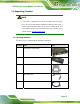
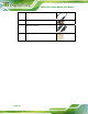
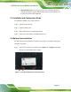
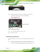
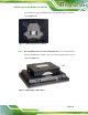
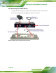
Table Of Contents
AUPS Series Power Module User Manual
Page 18
Figure 3-2: Top Cover Retention Screws (Top Panel)
Step 2: Install the battery pack into the AUPS Series. Make sure the battery pack is
connected to the battery connector on the board. (
Figure 3-3)
Figure 3-3: Battery Pack Installation
Step 3: Secure the battery pack with two retention screws.
Step 4: Replace the top cover. Step 0:
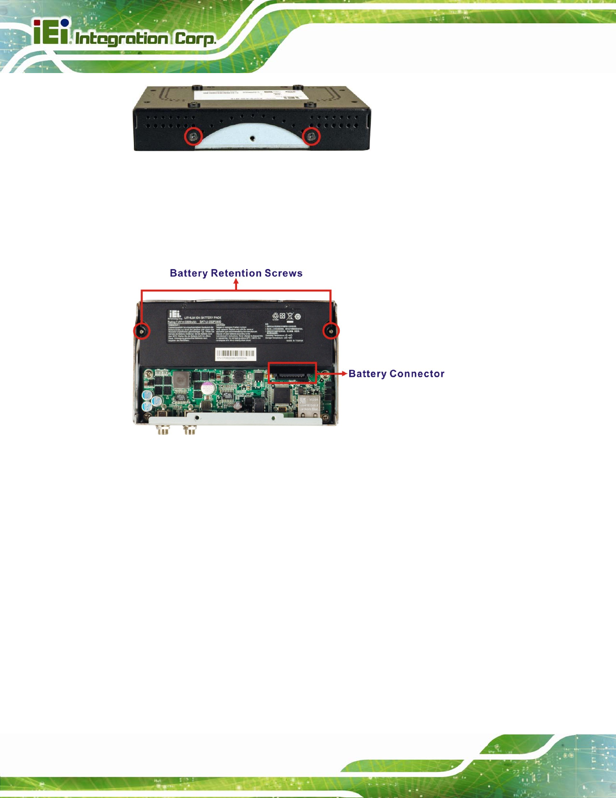
3.5 Mounting the AUPS Series
To mount the AUPS Series onto the rear panel of the AFOLUX panel PC, follow the steps
below.
Step 1: Install the mounting bracket onto the rear panel of the AFL panel PC. Align
the screw holes in the mounting bracket with the VESA screw holes in the rear of