
User Manual

AFL2-W15A-N270 Panel PC
Page 20
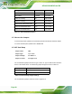
Description Label Type
CF card setup JCF1 2-pin header
Clear CMOS J_CMOS1 3-pin header
COM1 Pin 9 setting JP5 10-pin header
COM3 Pin 9 setting JP7 6-pin header
COM3 RX RS-232/422/485 select JP8 8-pin header
COM3 RS-232/422/485 select JP10 12-pin header
COM3 TX RS-422/485 select JP11 6-pin header
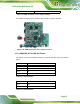
Table 2-2: AFL2-W15A-N270 Jumpers
2.7.1 Access the Jumpers
To access the jumpers, please remove the back panel and the internal aluminum chassis.
To remove the back panel, please refer to Section
2.6.
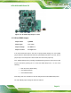
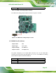
2.7.2 CF Card Setup
Jumper Label: JCF1
Jumper Type:
2-pin header
Jumper Settings:
See
Table 2-3
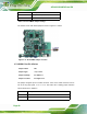
Jumper Location:
See
Figure 2-10
The CF Card Setup jumper sets the CF Type I card or CF Type II cards as either the slave
device or the master device. CF Card Setup jumper settings are shown in
Table 2-3.
CF Setup Description
Open Master (Default)
Closed Slave
Table 2-3: CF Card Setup Jumper Settings
The CF Card Setup jumper location is shown in Figure 2-10.