
User Manual


AFL2-W10A-N28 Panel PC
Page 44
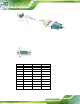
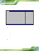
Figure 3-30: RJ-45 Serial Port Connector
Step 4: Secure the connector. Secure the serial device conn ector to the external
interface by tightening the two retention screws o n either side of th e connector.
Step 0:
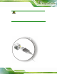
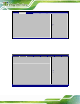
The DB-9 connector pin outs are listed below.
Figure 3-31: DB-9 Connector Pinout Locations
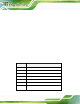
PIN NO. RS-232 RS-422 RS-485
1 DCD RX+ -
2 RX RX- -
3 TX TX+ DATA+
4 DTR TX- DATA-
5 GND - -
6 DSR - -
7 RTS - -
8 CTS - -
9 RI - -
Table 3-1: DB-9 Connector Pinout