
User Manual


AFL2-W10A-N28 Panel PC
Page 38
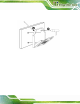
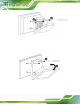
Figure 3-24: Secure System to V-Stand
Step 5: Align the V-Stand screw ho les with the pilot holes on the mounting area. Mount
the V-Stand by inserting the retention screws into the four pilot holes and
tightening them.
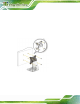
Step 6: Adjust the V-Stand to have a best viewin g angle to operate the system.Step 0:
Figure 3-25: Secure V-Stand to Mounting Area