
User Manual


AFL2-W10A-N28 Panel PC
Page 37
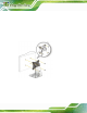
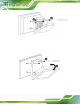
Step 1: Carefully mark the locations of the four V-Stand screw holes on the mounting
area. Drill four pilot holes at the marked locations for the V-Stand retention
screws.
Figure 3-23: Drill Pilot Holes for V-Stand
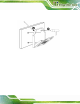
Step 2: Align the screw holes on the V-Stand with the VESA mount screw holes on the
system rear panel.
Step 3: Insert the four VESA mount screws into the four screw holes on the system rear
panel. Adjust the V-Stand to a proper position.
Step 4: Tighten until the screw shank is se cured against the rear panel.