
User Manual


AFL2-W10A-N28 Panel PC
Page 24
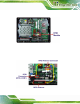
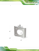
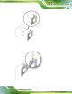
Step 6: Replace the internal cover and ba ck cover using previously removed retention
screws. Step 0:
3.6 AT/ATX Mode Selection
AT or ATX power mode can be used on the AFL2-W10A-N28. The selection is made
through an AT/ATX switch located on the bottom panel. To sele ct AT mode or ATX mode,
follow the steps below.
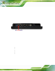
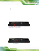
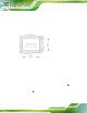
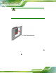
Step 1: Locate the AT/ATX switch on the bottom panel (
8Figure 3-9).
Figure 3-9: AT/ATX Switch Location
Step 2: Adjust the AT/ATX switch. Step 0:
3.6.1 AT Power Mode
With the AT mode selected, the power is controlled by a central power unit rather than a
power switch. The AFL2-W10A-N28 panel PC turns on automatically when the power is
connected. The AT mode benefits a production line to control multiple panel PCs from a
central management center and other applications includi ng:
ATM
Self-service kiosk
Plant environment monitoring system
Factory automation platfo rm
Manufacturing shop flow
3.6.2 ATX Power Mode
With the ATX mode selected, the AFL2-W10A-N28 panel PC goes in a standby mode
when it is turned off. The panel PC can be easily turned on via network or a power switch
in standby mode. Remote power control is perfect for advertising applications since the