
User Manual
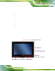


AFL2-W10A-N28 Panel PC
Page 7
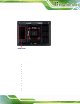
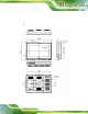
1.2.2 Rear Panel
The rear panel provides access to retent ion screw holes that support VESA mounting. The
HDD bay is protected by the HDD cover. Refer to
8Figure 1-5.
Figure 1-5: Rear View
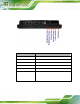
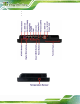
1.2.3 Bottom Panel
The bottom panel of the AFL2-W10A-N28 has the following connectors and switches
(
8Figure 1-6):
1 x 9 V ~ 36 V DC input power jack
1 x Audio line-out jack
1 x AT/ATX switch
1 x Clear CMOS switch
1 x DisplayPort connector
6 x Function keys
1 x GbE RJ-45 connector
1 x Digital micropho ne
1 x Power button
1 x Reset button
1 x RS-232 DB-9 connector (COM1)
1 x RS-232 RJ-45 connector (COM3)