
User Manual


AFL2-W10A-N28 Panel PC
Page 129
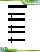
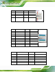
7.3.4 RS-422/485 RJ-45 Serial Port (COM2)
PIN NO. DESCRIPTION PIN NO. DESCRIP TIO N
1 RXD422+ 2 NC
3 RXD422- 4 NC
5 TXD422+/TXD485+ 6 NC
7 TXD422-/TXD485- 8 NC
Table 7-32: RS-422/485 Serial Port (COM2) Pino uts
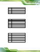
The serial device is connected to the system through the RJ-45 to COM port cable. The
DB-9 connector pinouts of the ca ble are listed below.
PIN NO. RS-422 RS-485
1 RX+ -
2 RX- -
3 TX+ DATA+
4 TX- DATA-
5 - -
6 - -
7 - -
8 - -
9 - -
Table 7-33: DB-9 Connector Pinout
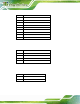
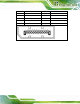
7.3.5 RS-232 RJ-45 Serial Ports (COM3)
PIN NO. DESCRIPTION PIN NO. DESCRIP TION
1 NDCD3 2 NDSR4
3 NRXD4 4 NRTS4
5 NTX4 6 NCTS4
7 NDTR4 8 NRI4
Table 7-34: RS-232 RJ-45 Serial Ports (COM3) Pinouts